Design For Forging Manufacturing Considerations
Manufacturing Knowledge Menu
About Forging Manufacturing
Design For Forging Manufacturing Considerations
Forging Manufacturing Design Considerations: For parts manufactured by forging that are produced in two-part impression dies, the designer should take into account the following: the parting line, the draft, the presence of ribs, bosses, webs, and recesses, and the machining allowance.
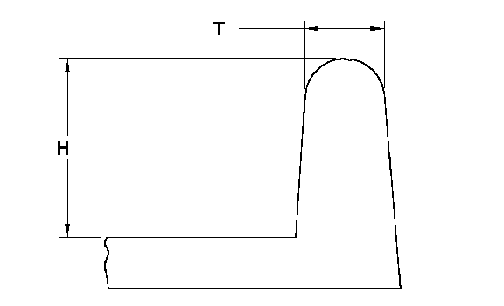
Rib height forging manufacturing design - the ratio of rib height (H) to thickness (T) in general should not exceed 6:1. As a general rule, the rib thickness should be equal to or less than the web thickness to avoid process defects.

Parting Line
The mating surfaces of the two halves of the die define a parting line around the edges of the forging as they come together. Determining the position of the parting line is a critical step in the forging design. The parting line should be indicated on the forging drawing. It is preferable that the parting line lie in one plane perpendicular to the axis of the die motion. It can be located such that one die half will be completely flat, and the line will surround the largest projected area of the piece. The angle of the surface at the parting line from the primary parting plane should not exceed 75o, in general, much shallower angles are preferred. It is important that the designer select the parting line such that no undercuts are in either die impression, since the forging must be ejected out of the die after it is made. The parting line location can be changed to control the grain direction given the above recommendations are fulfilled.
Draft
The forging must be designed such that adequate draft is present to facilitate removing the forging from the dies. Generally, all forged surfaces that lie parallel to the die motion are tapered. This taper also helps the flow into deeper die cavities. The draft should be specified by the angle with respect to the die-motion axis. It is conventional to specify a standard draft angle for all affected surfaces on a forging. Also, it is conventional to call for matching draft on both die halves to make surfaces of unequal depth meet at the parting line. Low-draft and no-draft forging can be produced in some metals, such as aluminum and brass. This is done in cases when reduction or elimination of draft yields significant benefits. Minimum draft angle for high tolerance forgings can be 0 deg. +/- .5 deg. . Standard draft angles should be at least 1deg. +.5 deg - minus .5 deg. .
Ribs, Bosses, Webs, and Recesses
It is easier to manage metal flow when the ribs and bosses are not too high and narrow, and the web is relatively thick and uniform. Deep recesses are easier to forge with spherical bottoms.
Machining Allowance
The machining allowance should allow for the worst-case buildup of draft and for all tolerances. Extra metal should be provided to at the critical machined surfaces away from the grain-flow pattern that occurs in the flash region near the parting line. Generally the machine allowance should be .06 inch for each machined surface.
Radii, Fillet
The largest reasonable radii at corners and fillet areas are optimal. Radii should blend tangent with draft surfaces. Forging radii are designed with the die design and requirements in consideration. Tolerances for minimum radii as follows:
Rib or Wall Height Minimum Fillet Radii
Less than 1.5 in. .13
1.50 to 3.00 in. .19
Over 3.00 in. .25
Edge Radii Edge Radii
Up to .120 1/2 Rib or Wall Thickness
.120 and Up .06 Min.
Dimensioning and Tolerancing
Establish the forging DRF (Datum Reference Plane) with the use of Datum Targets by way of machining centers. Sufficient pads or bosses should be included on the forging at the parting line. Typically, the machining center should be of adequate size with draft to facilitate fixturing. Details of the machining centers and datum requirements should be detailed on the forging drawing. Datum definition and machining center locations should be coordinated with the forging manufacturer and post machining manufacturer. Tolerance of length should be specified at .001/inch at a minimum. Tolerance of profile for each surface relative to the DRF is .020 and, should be considered minimum.
Wall Thickness
Maximum wall thickness is determined by manufacturer capabilities however, 10 inch wall should be considered maximum. Wall thickness of .20 over a span of 4.5 inches should be considered minimum.
Surface
Typically surface roughness of forged components should be specified at 64 RMS or rougher.
The tolerances adopted by the Drop Forging Association in 1937 (see accompanying table calculators) apply to forgings under 100 pounds each. Forging tolerances may either be "special" or "regular". Special tolerances are those which are particularly noted in the specifications and may state any or all tolerances in any way as required. Special tolerances apply only to the particular dimensions noted. In all cases where special tolerances are not specified, regular tolerances apply.
See forging definitions page for more!
References
Steel Die Forgings per. DIN-EN-102301
Related