Pressure Detector Circuits and Block Diagram Basics
Electronics, Instrumentation & Electrical Database
Pressure Detector Circuits and Block Diagram Basics
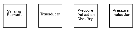
Within the block / circuit diagram illustrated below, the sensing element senses the pressure of the monitored system and converts the pressure to a mechanical signal. The sensing element supplies the mechanical signal to a transducer, as discussed above. The transducer converts the mechanical signal to an electrical signal that is proportional to system pressure. If the mechanical signal from the sensing element is used directly, a transducer is not required and therefore not used. The detector circuitry will amplify and/or transmit this signal to the pressure indicator. The electrical signal generated by the detection circuitry is proportional to system pressure. The exact operation of detector circuitry depends upon the type of transducer used. The pressure indicator provides remote indication of the system pressure being measured.
Link to this Webpage:
© Copyright 2000 -
2024, by Engineers Edge, LLC
www.engineersedge.com
All rights reserved
Disclaimer |
Feedback
Advertising
| Contact