Related Resources: instrumentation
Mechanical Design Tips for EMI Shielding
Applications and Design
Electronics Design and Engineering
Mechanical Design Tips for EMI Shielding
Any company involved in electronics packaging is concerned with CE/EMI demands on thier end products. As the use of electronics increases, and so do the frequencies. Therefore, these demands have to be taken into account at an early stage during the development of new products. In many cases, it is impossible to solve EMI problems at a PCB level, and is it necessary to shield the enclosures and cables.
Applications:
Shielding is a fast way to comply with legal demands or to prevent electromagnetic interference. Because no long-lasting development is required, it is a cost-effective method. Therefore shielding is used for smaller series or if a quick market introduction is needed. Besides that, it is also used for appliances with high radiation or sensitivity levels or for products of which little is known in advance, such as modular enclosures.
Radiation and conduction
Electromagnetic interference can be transferred by radiation and conduction. Conduction plays an important role for frequencies below 10 MHz. To prevent the interference transfer, cables and enclosures have to be shielded well with magnetically conductive materials. The lower the frequency, the thicker the shielding needs to be. For high frequencies (HF shielding, >40 MHz), only a very thin layer of highly conductive material is needed.
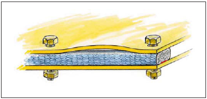
Figure 1. Deflection of parts because of too high stiffness of the gasket.
Avoid gaps
The higher the frequency, the shorter the wavelength. This means that with increasing frequency, the tolerable gap dimensions decrease. In other words, doors, panels and other parts need to be connected electrically on all sides. The easiest way to do this is with highly conductive EMI shielding gaskets. Most of them are self-adhesive for easy mounting.
To select the appropriate gasket, several aspects have to be taken into account, such as the rigidity of the construction, the distance between the fixings and the distance between the fixings and the construction materials used.
The allowed stiffness of the gasket depends on the rigidity of the construction and the distance between the fixings. If the gasket is too stiff, the door, lid or panel will deflect, causing gaps (Figure 1). Several kinds of gaskets have been developed especially for doors, combining a very large compression range, low closure force and high conductivity. Many of them can be used in existing products without changing the construction of the product.
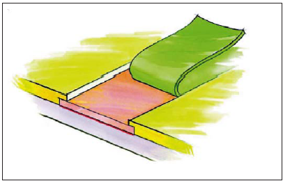
Figure 2. Metal tape with conductive self-adhesive to increase corrosion resistance.
Galvanic corrosion
The conductive layer on the outside of the gasket needs to be in the same galvanic range as the construction materials. Otherwise, galvanic corrosion will occur and the electrical conduction between the parts will be reduced, thus decreasing the shielding performance. Commonly used criteria include: no more than 0.3 volts for harsh environments (salt spray/weathering) and no more than 0.5 volts for benign environments (indoors, salt-free condensation only).
To obtain a contact surface within the same range as the conductive covering of the gaskets, a metal tape with conductive self-adhesive can be applied, such as masking tape with a smaller width. The paint should overlap the tape to increase bonding and corrosion resistance (Figure 2).
Another way to avoid galvanic corrosion is to make sure that the environmental influences do not reach the EMI shielding gasket by using, for example, a combined EMI/water seal. (Figure 3).
Some manufacturers of EMI shielding gaskets use carbon- containing layers on the outside to prevent corrosion of the gasket. But be aware that these are not galvanically compatible with many commonly used construction materials and that corrosion of the construction contact materials may be inevitable. EMI shielding gaskets with a conductive layer of reinforced Amucor® foil are much more compatible with materials like zinc-plated steel and aluminum and will prevent this kind of corrosion.
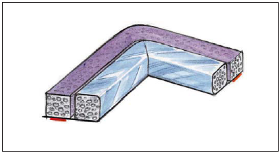
Figure 3. Combined EMI/water seal.
Displays and vent panels
Aside from connection between construction parts, displays and vent panels also need proper shielding. Displays can be provided with a sputtered, transparent conductive coating for HF shielding (>30 Mhz, Figure 4a) or a fine metal wire mesh for lower frequency/high performance shielding (Figure 4b). The conductive sputter layer can be coated directly on the display or on thin films to form smaller demands.
The shielding of the displays needs to be connected with the shielding of the enclosure to guarantee optimal damping. This can be done with a gasket or metal tape with conductive self-adhesive.
Vent panels are normally shielded with aluminum honeycomb vents, which provide excellent shielding performance with minimal loss of airflow. For superb shielding performance so-called cross-cell honeycombs vents are used. These vents consist of two or more layers of aluminum honeycomb, which are rotated 90 degrees (Figure 5). Honeycombs are normally applied with a rigid aluminum frame and a gasket of 2 to 5 mm for optimal connection with the construction.
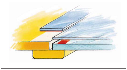
Figure 4a. Shielded display with transparent conductive foil.
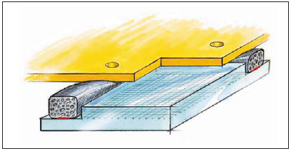
Figure 4b. Shielded display with laminated metal wire mesh.
Cables
To avoid radiation emission, power and signal cables need to be shielded or filtered. Shielding can be achieved with ready-made shielded cables, shielding tube and cable wrapping. Shielding tube consists of hollow braided metal wire, through which the cable or bundle of cables can be pulled. Cable wrapping is a knitted metal wire tape, which is wrapped around a cable or bundle of cables. Using this wrapping, branches can be made very easily.
Cable shielding always needs to be connected properly with the shielding of the enclosure, otherwise the cable will act as an antenna and shielding will be useless. For heavy-duty and military applications, shielded cable glands and special cable entry systems with compressed conductive rubber seals are commonly used.
For commercial applications and appliances that do not need a water seal, entry-shield is used in most cases. Entry-shield consists of two precompressed flexible strips of EMI shielding gasket, between which the cables are entered. This way, many cables can be entered simultaneously with minimal mounting, and it is very easy to add cables later (Figure 6).
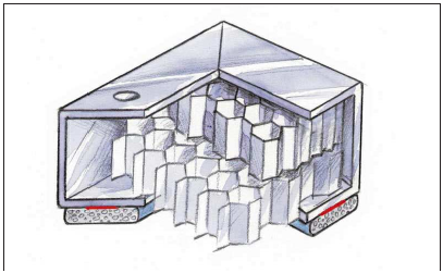
Figure 5. Cross-cell honeycomb vents.
Connectors
Connectors also need to be shielded or filtered and connected with a gasket. These gaskets can consist of 1 mm-thick die-cut material, which can be manufactured easily according to customer specifications, with little tooling costs (Figure 7).
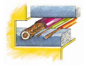
Figure 6. Entry-shield.
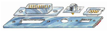
Figure 7. Connector gaskets.
Shielding at the source
If the source of the radiation or sensitivity is known, shielding should begin at this level. The interfering parts can be packed in a folded box or envelope of die-cut shielding foil with an insulating layer on the inside to avoid short-circuiting (Figure 8). It can also be done by soldering vertical metal strips on the PCB to create compartments. These compartments are closed by placing a lid of flexible die-cut shielding foil (Figure 9) or by pressing a soft foam sheet with a conductive surface against the strips (Figure 10). This final option allows many compartments to be shielded with just one single cover.
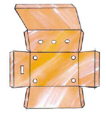
Figure 8. Shielded box of die-cut foil.
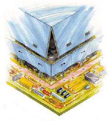
Figure 9. Shielding of parts of a PCB.
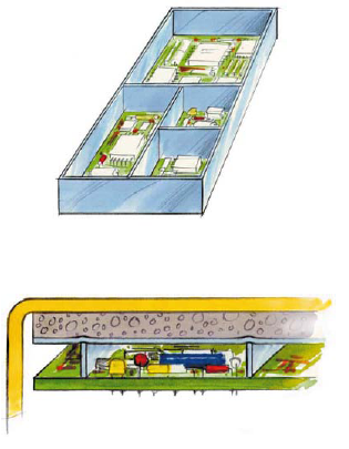
Figure 10. Compartments of a PCB.
Author
Fred Broekhuizen
Holland Shielding Systems
Original publish: Applied Microwave & Wireless
Link to this Webpage:
© Copyright 2000 -
2024, by Engineers Edge, LLC
www.engineersedge.com
All rights reserved
Disclaimer |
Feedback
Advertising
| Contact