Related Resources: hardware
T-Slot Profile Design per. BS 2485
Engineering ANSI Hardware Design Data
Engineering Metric Hardware Design Data
T-Slot Profile Design per. BS 2485
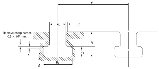
Dimensions in mm
(avoid pitch values in brackets as they lead to weakness)
|
Designations
of T-slot |
Width of
throat A1 |
Depth of
recess c1 |
Width
of recess B1 |
Overall
depth of T-slot H |
|||||
|
Nominal
|
Ordinary
(H12) |
For
use as tenon (HB) |
|||||||
|
min..
|
max.
|
min.
|
max.
|
min.
|
max
|
||||
|
M4
M5 |
5
6 |
+0.12
0 |
+0.18
0 |
10
11 |
11
12.5 |
3.5
5 |
4.5
6 |
8
11 |
10
13 |
|
M6
M8 |
8
10 |
+0.15
0 |
+0.22
0 |
14.5
16 |
16
18 |
7
7 |
8
8 |
15
17 |
18
21 |
|
M10
M12 M16 |
12 |
+.018
0 |
+0.022
0 |
19
23 30 |
21
25 32 |
8
9 12 |
9
11 14 |
20
23 30 |
25
28 36 |
|
M20
M24 |
22
28 |
+0.21
0 |
+.027
0 |
37
46 |
40
50 |
16
20 |
18
22 |
38
48 |
45
56 |
|
M30
M36 M42 |
36
42 48 |
+0.25
0 |
+0.033
0 |
56
68 80 |
60
2 85 |
25
32 36 |
28
35 40 |
61
74 84 |
71
85 95 |
|
M48
|
54
|
+0.30
0 |
+.046
0 |
90
|
95
|
40
|
44
|
94
|
106
|
|
Designations
of T-slot |
Chamfer 45°
or radius |
Pitch
P |
|||||
|
K
max. |
F
max. |
G
max. |
|||||
|
M4
M5 |
1.0
1.0 |
0.6
0.6 |
1.0
1.0 |
|
20
25 |
25
62 |
32
40 |
|
M6
M8 |
1.0
1.0 |
0.6
0.6 |
1.0 |
|
32
40 |
40
50 |
50
63 |
|
M10
M12 M16 |
1.0
1.0 1.0 |
0.6
1.0 1.0 |
1.0
1.0 1.0 |
(40)
(50) (63) |
50
63 80 |
63
80 100 |
80
100 125 |
|
M20
M24 |
1.6
2.5 |
1.0
1.0 |
1.0
1.0 |
(80)
100 |
100
125 |
125
160 |
160
200 |
|
M30
M36 M42 |
2.5
2.5 2.5 |
1.0
1.6 2.0
|
1.0
4.0 6.0
|
125
160 200 |
160
200 250 |
200
250 320 |
250
320 400 |
|
M48
|
2.5
|
2.0
|
6.0
|
250
|
320
|
400
|
500
|
Tolerance of T-slots
|
Pitch
mm |
Tolerance
mm |
|
20 to 25
|
±0.2
|
|
32 to 100
|
±0.3
|
|
125 to 250
|
±0.5
|
|
320 to 500
|
±0.8
|
Link to this Webpage:
© Copyright 2000 -
2024, by Engineers Edge, LLC
www.engineersedge.com
All rights reserved
Disclaimer |
Feedback
Advertising
| Contact