Related Resources: fluid flow
Pipe Enlargement and Reduction Head, Heat and Minor Losses Formula
Fluids Engineering
Hydraulic and Pneumatic Knowledge
Pipe Enlargement and Reduction Head, Heat and Minor Losses Formula
Pipe enlargements and reductions contribute to head loss that can be included in minor losses. For sudden enlargement of pipes, head loss equation 1.0 may be used:
hf = ( v1 - v2 )2 / ( 2 g ) - Equation 1.0
Where:
v1 and v2 = velocities of the liquid in the two pipe sizes (m/sec, ft/sec)
D1 and D2 = diameters respectively (m, ft )
Writing Eq. (1.0) in terms of pipe cross-sectional areas A1 and A2,
hf = [ 1 - A1 / A2 )2 ( v2 / ( 2 g ) ] - Equation 1.2
for sudden enlargement

Sudden pipe reduction
A1 / A2 |
0.00 |
0.20 |
0.10 |
0.30 |
0.40 |
0.50 |
0.60 |
0.70 |
0.80 |
0.90 |
1.00 |
Cc |
0.585 |
0.632 |
0.624 |
0.643 |
0.659 |
0.681 |
0.712 |
0.755 |
0.813 |
0.892 |
1.000 |
|---|
Figure 1.0 Sudden pipe enlargement and reduction.
For sudden contraction or reduction in pipe size as shown in Fig. 1.0, the head loss is calculated from
hf = ( 1 / Cc -1 ) v22 / ( 2 g ) Equation 1.3
where the coefficient Cc depends on the ratio of the two pipe crosssectional areas A1 and A2 as shown in Fig. 1.2.
Gradual enlargement and reduction of pipe size, as shown in Fig. 1.5, cause less head loss than sudden enlargement and sudden reduction. For gradual expansions, the following equation may be used:
hf = Cc ( v1 - v2 )2 / ( 2 g ) Equation 1.4
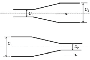
Fig 1.5 Gradual pipe enlargement and reduction.
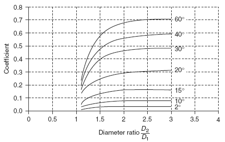
Figure 1.6 Gradual pipe expansion head loss coefficient.
where Cc depends on the diameter ratio D2/D1 and the cone angle β in the gradual expansion. A graph showing the variation of Cc with β and the diameter ratio is shown in Fig. 1.6.
Related:
- Pipe Flow Gradual Size Enlargement Formula and Calculator
- Pex (Cross-Linked Polyethylene) Specifications
- Pressure Drop Equivalent Length of Pipes and Fittings HVAC
- Loss of Air Pressure Due To Pipe Friction Table 1
- Loss of Pressure Through Screw Pipe Fittings
- Pressure Drop Along Pipe Length
- Pipe Friction Equations Within Pipe For Fluid Flow
- Xtra Strong (XS) Size Steel Pipe Weights TAble Calculator
Reference:
Piping Calculations Manual,
E. Shashi Menon, P.E.
2005
Link to this Webpage:
© Copyright 2000 -
2024, by Engineers Edge, LLC
www.engineersedge.com
All rights reserved
Disclaimer |
Feedback
Advertising
| Contact