Related Resources: Civil Engineering
Thrustblock Excel Spreadsheet Calculators
NOTE: Refunds are not awarded after excel files have been downloaded - review your membership agreement for details.
Applications and Design
Civil Engineering Applications
Thrustblock Excel Spreadsheet Calculators
Open - Download
Thrustblock Thrust Retraining Size Calculator
Concrete Thrust block Design for Pipe Angles, Tee, Wye, and Dead End per. NEH
Thrust control. Abrupt changes in pipeline grade, horizontal alignment, or reduction in pipe size normally require anchors or thrust blocks to absorb any axial thrust of the pipeline. Thrust control may also be needed at the end of the pipeline and at in-line control valves.
Thrust blocks and anchors must be large enough to withstand the forces tending to move the pipe, including those of momentum and pressure as well as forces due to expansion and contraction. The positioning of the thrust blocks must consider whether connections adjacent to the thrust block are capable of movement, as well as the anticipated direction of movement.
The internal pressure of a pipe acts perpendicular to any plane with a force equal to the pressure, P, times the area of the pipe, A. The radial forces within the pipe are balanced by the tension in the pipe wall. The axial components of pressure through a straight section are balanced by the same pressure in the opposite direction.
The pipe manufacturer's recommendations for thrust control shall be followed.
Example:
A 12-inch diameter pipe will be installed for an irrigation pipeline system. The pipe will be buried under 4 feet of soil and include 90 degree bends. The working pressure in the pipe will be 50 pounds per square inch. The soil surrounding the trench consists of silty clay.
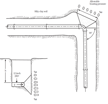
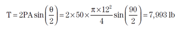
Thrust force on the pipe bend
Allowable soil bearing pressure to the depth to the center of the thrust block is
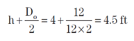
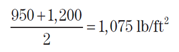
From Table 52-6 of NEH Part 636.5207, the allowable bearing capacity for silty clay soil at a depth of 4 feet is 950 lb/ft 2 and 1,200 lb/ft 2 at 5 feet. The allowable bearing capacity at 4.5 feet may be determined by an average.
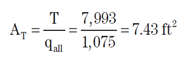
Area of thrust block required
The following table provides the approximate thrust generated at fittings for each 100 psi of water pressure.
|
Thrust at Fittings in Pounds at 100 psi Water Pressure
|
|||
| PIPE SIZE (INCHES) |
90° BEND | 45° BEND | VALVES, TEES AND DEAD ENDS |
| 4" | 2,600 | 1,420 | 1,850 |
|---|---|---|---|
| 6" | 5,400 | 2,900 | 3,800 |
| 8" | 9,300 | 5,000 | 6,500 |
| 10" | 13,900 | 7,550 | 10,850 |
| 12" | 19,700 | 10,800 | 13,900 |
| 16" | 34,000 | 18,600 | 24,200 |
| 20" | 52,200 | 28,400 | 37,000 |
| 24" | 74,300 | 40,400 | 52,700 |
| 30" | 114,100 | 62,000 | 80,800 |
| 36" | 163,400 | 88,700 | 115,600 |
If size of thrust block has not been specified by engineer, the following example shows steps required to determine the bearing area. Assume thrust block is resisting horizontal thrust at an 8", 90° bend; pipeline to be tested at 200 psi and the soil is sand.
• Check the above table and you will find that the thrust developed on an 8", 90° bend is 9300 lbs. for each 100 lbs. of water pressure. Since the pipeline is to be tested at 200 psi, the total thrust is 2 x 9300 or 18,600 lbs.
• In the table below, you will find that the bearing power of sand is 2000 lbs. per square foot. Dividing the total force of 18,600 lbs. by 2000 lbs., gives a total required thrust backing of 9.3 square feet or an area slightly over 3 ft. x 3 ft.
|
SAFE BEARING LOAD
|
|
|
TYPE OF SOIL
|
LBS. PER SQ. FT.
|
|
Muck, Peat, etc.
|
0
|
|
Soft Clay
|
1,000
|
|
Sand
|
2,000
|
|
Sand and Gravel
|
3,000
|
|
Sand and Gravel Cemented with Clay
|
4,000
|
|
Hard Pan
|
10,000
|
Link to this Webpage:
© Copyright 2000 -
2024, by Engineers Edge, LLC
www.engineersedge.com
All rights reserved
Disclaimer |
Feedback
Advertising
| Contact