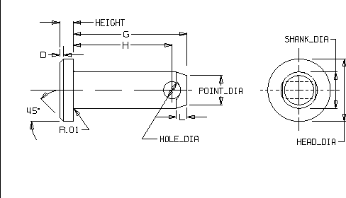
ANSI Clevis Pin Size Chart Table
ANSI Clevis Pin Size Chart Table
There are two main types of clevis pins: threaded and unthreaded. Unthreaded clevis pins have a domed head at one end and a cross-hole at the other end. A cotter pin (USA usage) or split pin is used to keep the clevis pin in place. Threaded clevis pins have a partially threaded shank on one end and a formed head on the other. The formed head has a lip, which acts as a stop when threading the pin into the shackle, and a flattened tab with a cross-hole. The flattened tab allows for easy installation of the pin and the cross-hole allows the pin to be moused.
A bolt can function as a clevis pin, but a bolt is not intended to take the lateral stress that a clevis pin must handle. Normal bolts are manufactured to handle tension loads, whereas clevis pins and bolts are designed to withstand shearing forces.
Clevis pins should be closely fitted to the holes in the clevis to limit wear and reduce the failure rate of either the pin or the clevis.
Clevis Pin Dimensional Size Chart Data
|
BASIC |
SHANK |
HEAD |
HEIGHT |
D |
HOLE |
POINT |
G |
H |
L |
|
.1875 |
0.186 |
0.320 |
0.070 |
0.020 |
0.088 |
0.150 |
0.580 |
0.504 |
0.055 |
|
.25 |
0.248 |
0.380 |
0.100 |
0.030 |
0.088 |
0.210 |
0.770 |
0.692 |
0.088 |
|
.3125 |
0.311 |
0.440 |
0.100 |
0.030 |
0.119 |
0.260 |
0.940 |
0.832 |
0.071 |
|
.375 |
0.373 |
0.510 |
0.130 |
0.030 |
0.119 |
0.330 |
1.060 |
0.958 |
0.0710 |
|
.4375 |
0.436 |
0.570 |
0.160 |
0.040 |
0.119 |
0.390 |
1.190 |
1.082 |
0.071 |
|
.5 |
0.496 |
0.630 |
0.160 |
0.040 |
0.151 |
0.440 |
1.3600 |
1.223 |
0.089 |
|
.625 |
0.621 |
0.820 |
0.210 |
0.060 |
0.151 |
0.560 |
1.610 |
1.473 |
0.089 |
|
.75 |
0.746 |
0.940 |
0.260 |
0.070 |
0.182 |
0.680 |
1.910 |
1.739 |
0.110 |
|
.875 |
0.871 |
1.040 |
0.320 |
0.090 |
0.182 |
0.800 |
2.160 |
1.989 |
0.110 |
|
1 |
0.996 |
1.190 |
0.350 |
0.100 |
0.182 |
0.930 |
2.410 |
2.239 |
0.110 |
