|
WIND LOADING ANALYSIS - MWFRS and Components/Cladding
|
|
Per ASCE 7-02
Code for Low-Rise, Enclosed Buildings with h <= 60' and Roof q <= 45o
|
|
Using Method 1:
Simplified Procedure (Section 6.4)
|
|
|
|
|
|
|
|

|
|
|
|
|
Input Data:
|
|
|
|
|
|
|
|
|
|
|
Wind Speed, V =
|
|
mph (Wind
Map, Figure 6-1)
|
|
|
|
|
|
Bldg.
Classification =
|
|
(Table 1-1)
|
|
|
|
|
|
Exposure Category =
|
|
(Sect. 6.5.6)
|
|
|
|
|
|
Ridge Height, hr =
|
|
ft. (hr >= he)
|
|
|
|
|
|
|
Eave Height, he =
|
|
ft. (he <= hr)
|
|
|
|
|
|
|
Building Width, W =
|
|
ft. (Normal to Building Ridge)
|
|
|
|
|
|
Building Length, L
=
|
|
ft. (Parallel to Building Ridge)
|
|
|
|
|
|
Roof Type =
|
|
(Gable or Monoslope)
|
|
|
|
|
|
Wall C&C Name =
|
|
(Girt, Siding, Wall, or Fastener)
|
|
|
|
|
|
Wall C&C Eff.
Area =
|
|
ft.^2 (for Component/Cladding)
|
|
|
|
|
|
Roof C&C Name =
|
|
(Purlin, Joist, Decking, or Fastener)
|
|
|
|
|
|
Roof C&C Eff.
Area =
|
|
ft.^2 (for Component/Cladding)
|
|
|
|
|
|
Overhang Eff. Area
=
|
|
ft.^2 (for Component/Cladding)
|
|
|
|
|
|
Hurricane Region?
|
|
|
|
|
|
|
|
|
|
|
|
|
|
|
|
|
|
|
|
Resulting
Parameters and Net Design Pressures:
|
|
|
|
|
|
|
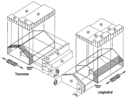
For Transverse Direction:
|
(wind perpendicular to
ridge)
|
|
|
|
|
Roof Angle, q =
|
|
deg.
|
|
|
|
|
|
|
Mean Roof Ht., h =
|
|
ft. (h = he for q < 10 deg.)
|
|
|
|
|
Adjustment Factor, l =
|
|
(adjusts for height and
exposure)
|
|
|
|
|
Importance Factor, I =
|
|
(Table 6-1)
|
|
|
|
|
|
|
Wall & Roof End
Zone Width, a =
|
|
ft. (use: "2*a" for MWFRS,
"a" for C&C)
|
|
|
|
|
|
|
|
|
|
|
|
|
|
Transverse
MWFRS Net Pressures (psf)
|
|
|
|
Location
|
Direction
|
Zone
|
Load Case 1
|
|
|
|
|
A = end
zone of wall
|
Horizontal
|
A
|
|
|
|
|
|
B = end
zone of roof
|
Horizontal
|
B
|
|
|
|
|
|
C =
interior zone of wall
|
Horizontal
|
C
|
|
|
|
|
|
D =
interior zone of roof
|
Horizontal
|
D
|
|
|
|
|
|
E = end
zone of windward roof
|
Vertical
|
E
|
|
|
|
|
|
F = end
zone of leeward roof
|
Vertical
|
F
|
|
|
|
|
|
G =
interior zone of windward roof
|
Vertical
|
G
|
|
|
|
|
|
H =
interior zone of leeward roof
|
Vertical
|
H
|
|
|
|
|
|
|
|
|
|
|
|
|
|
|
|
For Longitudinal
Direction:
|
(wind parallel to ridge)
|
|
|
|
|
Roof Angle, q =
|
|
deg.
(assumed)
|
|
|
|
|
Mean Roof Ht., h =
|
|
ft. (h =
(hr+he)/2)
|
|
|
|
|
Adjustment Factor, l =
|
|
(adjusts for height and exposure)
|
|
|
|
|
|
|
|
|
|
|
|
|
|
Longitudinal
MWFRS Net Pressures (psf)
|
|
|
|
Location
|
Direction
|
Zone
|
Load Case 1
|
|
|
|
|
A = end
zone of wall
|
Horizontal
|
A
|
|
|
|
|
|
B = end
zone of roof
|
Horizontal
|
B
|
|
|
|
|
|
C =
interior zone of wall
|
Horizontal
|
C
|
|
|
|
|
|
D =
interior zone of roof
|
Horizontal
|
D
|
|
|
|
|
|
E = end
zone of windward roof
|
Vertical
|
E
|
|
|
|
|
|
F = end
zone of leeward roof
|
Vertical
|
F
|
|
|
|
|
|
G =
interior zone of windward roof
|
Vertical
|
G
|
|
|
|
|
|
H =
interior zone of leeward roof
|
Vertical
|
H
|
|
|
|
|
|
|
|
|
|
|
|
|
|
|
|
|
|
|
|
|
|
|
|
|
|
|
|
|
|
|
|
|
|
|
|
Total
Design MWFRS Horizontal Load (kips)
|
|
|
|
|
Transverse
|
Longitudinal
|
|
|
|
|
Load Case 1
|
Load Case 2
|
Min. Load
|
Load Case 1
|
Load Case 2
|
Min. Load
|
|
|
|
|
|
|
|
|
|
|
|
|
|
|
Formulas:
|
|
|
|
|
|
|
|
|
|
Ph(Trans) =
((Pc*(L-4*a)+Pa*4*a)*he+(Pd*(L-4*a)+Pb*4*a)*(hr-he))/1000
|
|
|
|
Ph(Trans)(min) =
P(min)*L*hr/1000 , where: P(min) = 10.0 psf on projected area
|
|
|
|
|
|
|
|
|
Ph(Long)(min) =
P(min)*W*(hr+he)/2/1000 , where: P(min) = 10.0 psf on full area
|
|
|
|
|
|
|
|
|
|
|
|
|
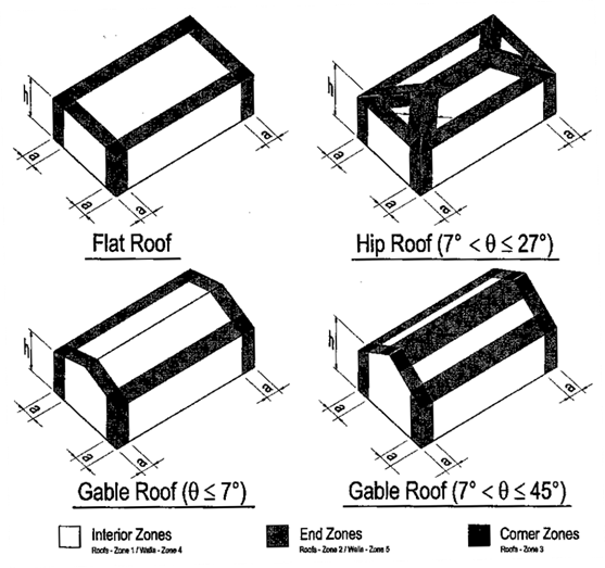
Components
& Cladding Net Pressures (psf)
|
|
|
|
Item
|
Location
|
Zone
|
Pos. (+)
|
Neg. (-)
|
|
|
|
|
4 =
interior zone of wall
|
4
|
|
|
|
|
|
|
|
5 = end
zone of wall
|
5
|
|
|
|
|
|
|
|
1 =
interior zone of roof
|
1
|
|
|
|
|
|
|
2 = end
zone of roof
|
2
|
|
|
|
|
|
|
|
3 = corner
zone of roof
|
3
|
|
|
|
|
|
Roof
Overhang
|
2 = end
zone of o.h.
|
2
|
---
|
|
|
|
|
|
|
3 = corner
zone of o.h.
|
3
|
---
|
|
|
|
|
|
|
|
|
|
|
|
|
|
|
Notes: 1.
|
For Method 1: Simplified
Procedure of Section 6.4 to be used for an enclosed low-rise building
|
|
to determine the design
wind loads, all of the following nine conditions of 6.4.1.1 must be met:
|
|
a. Building is a simple diaphragm
building, in which wind loads are transmitted through floor
|
|
and roof diaphragms to the vertical
Main Wind-Force Resisting System (MWFRS).
|
|
|
b. Building is a low-rise building where
mean roof height, h <= 60 ft., and h <= min. of L or W.
|
|
c. Building is enclosed and conforms to
wind-borne debris provisions of Section 6.5.9.3.
|
|
d. Building is a regular shaped building,
having no unusual geometrical irregularity.
|
|
|
f. Building is not classified as a
flexible building so it is considered "rigid".
|
|
|
|
g. Building is not subject to across-wind
loading, vortex shedding, etc.
|
|
|
|
h. Building has no expansion joints or
separations.
|
|
|
|
|
|
i. Building is not subject to topographic
effects, no abrupt topographic changes.
|
|
|
j. Building has an approximately
symmetrical cross section in each direction with either a
|
|
flat roof, or gable roof with q <= 45 degrees.
|
|
|
|
|
|
|
Wind pressures (ps30) in Figures 6-2 and 6-3 were prepared based on following
assumptions:
|
|
a. Mean roof height, h = 30 ft. ,
Exposure category = B , Importance factor, I =1.0
|
|
|
b. Velocity pressure exposure coefficient,
Kz = 0.70
|
|
|
|
|
|
c. Directionality factor, Kd = 0.85 ,
Topographic factor, Kzt = 1.0
|
|
|
|
|
d. Internal pressure coefficients, GCpi =
+0.18, -0.18 (enclosed building)
|
|
|
|
e. MWFRS pressure coeff's. from Figure
6-10, and C&C pressure coeff's. from Figure 6-11.
|
|
f. Design wind pressure, Ps = l*I*ps30, in
psf.
|
|
|
|
|
|
|
Design wind pressures are
net pressures (sum of external and internal pressures).
|
|
|
|
Wall net pressure for
MWFRS is total for both windward and leeward walls.
|
|
|
|
|
(+) and (-) signs signify
wind pressures acting toward & away from respective surfaces.
|
|
|
|
If pressures for Zones
"B" and "D" < 0, assume = 0.
|
|
|
|
|
|
|
For the design of the longitudinal MWFRS use
roof angle, q = 0 degrees.
|
|
|
|
|
|
|
|
|
|
|
Both load cases 1 and 2 are be checked for
roof angle, 25 degrees < q
<= 45 degrees.
|
|
|
|
|
|
|
|
|
|
|
The total design MWFRS horizontal load is the
total horizontal wind load on either the length (L)
|
|
|
|
|
|
|
|
|
|
or the width (W) of the
building respectively assuming one end zone of a width = 2*a.
|
|
|
|
Minimum wind load for
MWFRS design shall be 10 psf applied on projected vertical plane.
|
|
Minimum wind load for
C&C shall be 10 psf acting in either direction normal to surface.
|
|
|
|
References:
|
|
|
|
|
|
|
|
|
a. ASCE 7-02 Standard, "Minimum
Design Loads for Buildings and Other Structures".
|
|
b. "Guide to the Use of the Wind Load
Provisions of ASCE 7-02"
|
|
|
|
|
by: Kishor C. Mehta and James M.
Delahay (2004).
|
|
|
|
|
|
|
|
|
|
|
|
|
|
(continued)
|
|
|
|
|
|
|
|
|
|
|
|
|
|
|
|
|
|
|
|
|
|
|
|
|
|
|
|
|
|
|
|
|
|
|
|
|
|
|
|
|
|
|
|
|
|
|
|
|
|
|
|
|
|
|
|
|
|
|
|
|
|
|
|
|
|
|
|
|
|
|
|
|
|
|
|
|
|
|
|
|
|
|
|
|
|
|
|
|
|
|
|
|
|
|
|
|
|
|
|
|
|
|
|
|
|
|
|
|
|
|
|
|
|
|
|
|
|
|
|
|
|
|
|
|
|
|
|
|
|
|
|
|
|
|
|
|
|
|
|
|
|
|
|
|
|
|
|
|
|
|
|
|
|
|
|
|
|
|
|
|
|
|
|
|
|
|
|
|
|
|
|
|
|
|
|
|
|
|
|
|
|
|
|
|
|
|
|
|
|
|
|
|
|
|
|
|
|
|
|
|
|
|
|
|
|
|
|
|
|
|
|
|
|
|
|
|
|
|
|
|
|
|
|
|
|
|
|
|
|
|
|
|
|
MWFRS -
Wind Zones
|
|
|
|
|
|
|
|
|
|
|
|
|
|
|
|
|
|
|
|
|
|
|
|
|
|
|
|
|
|
|
|
|
|
|
|
|
|
|
|
|
|
|
|
|
|
|
|
|
|
|
|
|
|
|
|
|
|
|
|
|
|
|
|
|
|
|
|
|
|
|
|
|
|
|
|
|
|
|
|
|
|
|
|
|
|
|
|
|
|
|
|
|
|
|
|
|
|
|
|
|
|
|
|
|
|
|
|
|
|
|
|
|
|
|
|
|
|
|
|
|
|
|
|
|
|
|
|
|
|
|
|
|
|
|
|
|
|
|
|
|
|
|
|
|
|
|
|
|
|
|
|
|
|
|
|
|
|
|
|
|
|
|
|
|
|
|
|
|
|
|
|
|
|
|
|
|
|
|
|
|
|
|
|
|
|
|
|
|
|
|
|
|
|
|
|
|
|
|
|
|
|
|
|
|
|
|
|
|
|
|
|
|
|
|
|
|
|
|
|
|
|
|
|
|
|
|
|
|
|
|
|
|
|
|
|
|
|
|
|
|
|
|
|
|
|
|
|
|
|
|
|
|
|
|
|
|
|
|
|
|
|
|
|
|
|
|
|
|
|
|
|
|
|
|
|
|
|
|
|
|
|
|
|
|
|
|
|
|
|
|
|
|
|
|
|
|
|
|
|
|
|
|
|
|
|
|
|
|
|
|
|
|
|
|
|
|
|
Components
and Cladding - Wind Zones
|
|
|
|
|
|
|
|
|
|
|
|
|
|