Related Resources: calculators
Time to Freeze Piping Formulas and Calculator
Fluids Engineering and Design
Hydraulic and Pneumatics
Time to Freeze Outdoor / Indoor Piping Formulas and Calculator ASHRAE Freeze Protection.
It is important to recognize that insulation reduces heat flow however it does not stop it completely. Piping located outdoors, or indoors in unheated areas, is subject to freezing. This is especially true for pipe systems containing standing water. Insulation will delay but not prevent freezing of still water or water flowing at a rate insufficient for the available heat content to offset the heat loss. The time required for standing water to cool to 32 °F can be estimated with the following equation from 2019 ASHRAE Fundamental Handbook:
Time to Freeze Nomenclature
θ = ρ Cp π ( D1 / 2 )2 ( RT ) ln [ ( ti - ta ) / ( tf - ta ) ]
As a conservative assumption for insulated pipes, thermal resistances of pipe walls and exterior air film are usually neglected.
Resistance of the insulation layer for a unit length of pipe is calculated as:
RT = 12 ln ( D3 / D2 ) / ( 2 π k )
Where:
θ = time for water to cool to freezing, h
ρ = density of liquid (water = 62.4 lb/ft3)
Cp = specific heat of water = 1.0 Btu/lb F
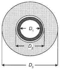
D1 = inside diameter of pipe, ft
D2 = inner diameter of insulation, ft
D3 = outer diameter of insulation, ft
RT = combined thermal resistance of pipe wall, insulation, and
exterior air film (for a unit length of pipe), ft · °F · h/Btu
k = thermal conductivity of insulation, Btu·in/h·ft2·°F
ta = ambient air temperature, ºF
ti = initial water temperature, ºF
tf = freezing temperature of fluid, ºF
When appropriate, the piping system design should include thermostatically controlled valves to automatically drain the system when a low-limit temperature sensor detects a fall in temperature below a predetermined set point – usually 35 ºF. Once outdoor temperature falls below freezing, cooling water is rarely required to maintain ambient conditions. In these cases, the controls should include a manual reset to prevent refilling the system after a shutdown initiated by the freeze protection system.
Table 1.0 Typical Time to Cool Water to Freezing, h
Nominal Pipe Size, NPS |
Insulation Thickness, in. |
|||||
0.5 |
1 |
1.5 |
2 |
3 |
4 |
|
1/2 |
0.1 |
0.2 |
0.2 |
0.3 |
- |
- |
1 |
0.3 |
0.4 |
0.5 |
0.6 |
0.8 |
- |
1 1/2 |
0.4 |
0.8 |
1.0 |
1.3 |
1.5 |
- |
2 |
0.6 |
1.1 |
1.4 |
1.7 |
2.2 |
2.5 |
3 |
0.9 |
1.7 |
2.3 |
2.9 |
3.7 |
4.5 |
4 |
1.3 |
2.4 |
3.3 |
4.1 |
5.5 |
6.6 |
5 |
1.6 |
3.0 |
4.3 |
5.4 |
7.4 |
9.1 |
6 |
1.9 |
3.7 |
5.3 |
6.9 |
9.4 |
11.7 |
8 |
- |
5.3 |
7.6 |
9.6 |
13.7 |
16.9 |
10 |
- |
6.5 |
10.2 |
12.9 |
17.9 |
22.3 |
12 |
- |
8.8 |
12.5 |
15.8 |
22.1 |
27.7 |
Table 1.0 shows estimated time to freezing, calculated using these equations for the specific case of still water with ti = 42°F and ta = –18°F. When unusual conditions make it impractical to maintain protection with insulation or flow, a hot trace pipe or electric resistance heating cable is required along the bottom or top of the water pipe. The heating system then supplies the heat lost through the insulation. Clean water in pipes usually supercools several degrees below freezing before any ice is formed. Then, upon nucleation, dendritic ice forms in the water and the temperature rises to freezing. Ice can be formed from water only by the release of the latent heat of fusion (144 Btu/lb) through the pipe insulation. Well-insulated pipes may greatly retard this release of latent heat. Gordon (1996) showed that water pipes burst not because of ice crystal growth in the pipe, but because of elevated fluid pressure within a confined pipe section occluded by a growing ice blockage.
Note: Assumes initial temperature = 42°F, ambient air temperature = –18°F, and insulation thermal conductivity = 0.30 Btu·in/h·ft2·°F. Thermal resistances of pipe and air film are neglected. Different assumed values yield different results.
Related:
- Boiling and Freezing Point Properties of Selected Substances
- Thermodynamic Properties Common Liquids , Solids, and Foods
- Wind Chill Calculator and Equations
- Thermal Conductivity Conversions Calculator
- Insulation Material Thermal Conductivity Chart
Reference:
- ASHRAE Fundamental Handbook, 1997
- ASHRAE Fundamental Handbook, 2019
Link to this Webpage:
© Copyright 2000 -
2024, by Engineers Edge, LLC
www.engineersedge.com
All rights reserved
Disclaimer |
Feedback
Advertising
| Contact