Related Resources: calculators
Snap Ring Groove Stress and Failure Formulas and Calculator
ANSI Hardware Guide
Metric Engineering Hardware Guide
Retaining Snap Ring Groove Stress and Failure Formulas and Calculator
The most common type of groove failure is yielding of the groove material that occurs when the thrust load, applied through the retaining ring against the corner of the groove, exceeds the compressive yield strength of the groove. This yielding of the groove results from a low compressive yield strength of the groove material, and allows the ring to tilt and come out of the groove, moment across the cross-section of the ring generates a tensile stress that is highest at the interior diameter of the ring. If the maximum stress is greater than the yield strength of the ring material, the ring ID will grow and the ring will become permanently dished in shape. To determine the thrust load capacity of a ring based on groove deformation, the allowable angle of ring deflection must be calculated, then the thrust load based on groove yield can be determined.
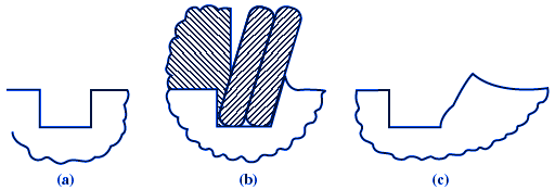
Illustration:
(a) Retaining ring groove as-designed.
(b) Retaining ring yielding and groove under loading.
(c) Groove after yielding event.
Courtesy (Spirolox Retaining Rings)
Thrust load Pg which estimates groove deformation equation:
Pg = ( π D d Sy ) / K
Where:
Ps = Thrust force ( lbf, N ),
D = Shaft or housing diameter (in, mm),
d = Retaining ring groove depth (in, mm),
t = Retaining ring thickness (in, mm),
Sy = Yield stength of the groove material (lb/in2, N/mm2)
K = Factor of safety
Keep units consitant, in with lb/in2 and mm with N/mm2.
Related:
- Retaining Snap Ring Stress and Failure Formulas and Calculator
- Retaining Rings Types and Applications
- Centrifugal Capacity Retaining Snap Rings
- Internal Retaining Snap Ring Sizes and Groove Design Chart
- Internal Retaining Snap Ring Sizes and Groove Design Bore Sizes 3.062 - 5.000
- Internal Retaining Snap Ring Sizes and Groove Design Chart Sizes 5.250 - 8.250
- Internal Retaining Snap Ring Sizes and Groove Design sizes 1.562 to 3.000
- Metric Tapered Retaining Snap Rings Size Chart
References:
Machinery's Handbook, 30th edition
Link to this Webpage:
© Copyright 2000 -
2024, by Engineers Edge, LLC
www.engineersedge.com
All rights reserved
Disclaimer |
Feedback
Advertising
| Contact