Related Resources: calculators
Lag Screws in Wood Pullout Resistance Force Formulae and Calculator
Strength Mechanics of Materials
Beam Deflections, Stress Analysis and Engineering
Civil Engineering and Design
Lag Screws in Wood Pullout Withdraw Resistance Force Formulae and Calculator
Lag screws are commonly used because of their convenience, particularly where it would be difficult to fasten a bolt or where a nut on the surface would be objectionable. Commonly available lag screws range from about 5.1 to 25.4 mm (0.2 to 1 in.) in diameter and from 25.4 to 406 mm (1 to 16 in.) in length. The length of the threaded part varies with the length of the screw and ranges from 19.0 mm (3/4 in.) with the 25.4- and 31.8-mm (1- and 1-1/4-in.) screws to half the length for all lengths greater than 254 mm (10 in.). Lag screws have a hexagonal-shaped head and are tightened by a wrench (as opposed to wood screws, which have a slotted head and are tightened by a screw driver). The following equations for withdrawal and lateral loads are based on lag screws having a base metal average tensile yield strength of about 310.3 MPa (45,000 lb/in2) and an average ultimate tensile strength of 530.9 MPa (77,000 lb/in2).
Preview Lag Screws in Wood Pullout Withdraw Resistance Force Calculator
The maximum direct withdrawal load of lag screws from the side grain of seasoned wood is given by:
p = 125.4 G3/2 D3/4 L (Metric SI Units)
p = 8,100 G3/2 D3/4 L (inch lbs Units)
Where:
p = Maximum withdrawal load (N, lb),
D = Shank diameter (mm, in.),
G = Specific gravity of the wood based on ovendry weight and volume at 12% moisture content,
L = Length (mm, in.) of penetration of the threaded part. (The NDS and LRFD use ovendry weight and volume as a basis.)
Lag screws, like wood screws, require prebored holes of the proper size . The lead hole for the shank should be the same diameter as the shank. The diameter of the lead hole for the threaded part varies with the density of the wood:
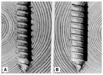
A, Clean-cut, deep penetration of thread
made by lag screw turned into a lead hole of proper
size, and B, rough, shallow penetration of thread
made by lag screw turned into oversized lead hole.
For low-density softwoods, such as the cedars and white pines, 40% to 70% of the shank diameter; for Douglas-fir and Southern Pine, 60% to 75%; and for dense hardwoods, such as oaks, 65% to 85%. The smaller percentage in each range applies to lag screws of the smaller diameters and the larger lubricants should be used on the screw to facilitate turning, and lead holes slightly larger than those recommended for maximum efficiency should be used with long screws.
In determining the withdrawal resistance, the allowable tensile strength of the lag screw at the net (root) section should not be exceeded. Penetration of the threaded part to a distance about seven times the shank diameter in the denser species (specific gravity greater than 0.61) and 10 to 12 times the shank diameter in the less dense species (specific gravity less than 0.42) will develop approximately the ultimate tensile strength of the lag screw. Penetrations at intermediate densities may be found by straight-line interpolation.
The resistance to withdrawal of a lag screw from the end grain surface of a piece of wood is about three-fourths as great as its resistance to withdrawal from the side-grain surface of the same piece.
- Nail in Wood Pullout Withdraw Resistance Force Formulae and Calculator
- Pressed Drift Pin Bolts in Wood Force Formulae and Calculator
- Wood Engineering Properties (Specific Gravity) for Hardwoods
- Wood Engineering Properties (Specific Gravity) #2
- Wood Engineering Properties (Specific Gravity) #3 Engineering Properties
- Density of Wood Equation and Calculator
- Wood Screw Sizes and Design Data
- Pilot Hole Drill Sizes for Wood Screws
- Pilot Holes for American Wood Screws
- American Wood Screws
Special Note to Non-Engineers
We think it's great that you're here on Engineers Edge, but know that this technical data is written for engineers and designers. Engineers Edge is an engineering and design consulting, training and publishing firm and does not provide extended support to our general web site visitors. There is a feedback form available and any and all professional comments are welcome.
References:
- AF&PA. 1997. National design specification for wood construction. Washington, DC: American Forest & Paper Association.
- ASCE. 1995. Standard for load and resistance factor design (LRFD) for engineered wood construction. Washington, DC:
- American Society of Civil Engineers. ASCE. 1996. Mechanical connections in wood structures. Washington, DC: American Society of Civil Engineers.
Link to this Webpage:
© Copyright 2000 -
2024, by Engineers Edge, LLC
www.engineersedge.com
All rights reserved
Disclaimer |
Feedback
Advertising
| Contact