Related Resources: calculators
Journal Bearing Lubrication Analysis Formulas and Calculator
Machine Design Applications
Bearings Engineering and Design
Fluids, Lubrication Design and Engineering
Journal Bearing Hydrodynamic Lubrication Analysis Equation and Calculator
The primary advantage of a fluid film bearing is often thought of as the lack of contact between rotating parts and thus, infinite life. In a pure sense, this is true, but other complications make this a secondary reason for using these bearings. During startup there is momentary metal-to-metal contact and foreign material in the lubricant or excessive vibration can limit the life of a fluid film bearing. For these reasons, special care must be taken when selecting and implementing a lubrication system and special vibration monitoring techniques must be applied. The most important aspects of the health and longevity of a fluid film bearing are proper selection, proper installation, proper lubrication, and the alternating hydrodynamic loads imposed on the bearing surface by relative shaft-to-bearing vibration.
There are three basic components of a journal or sleeve bearing: journal or shaft, bushing or bearing, and lubricant. Grooving and Oil Feeding. Grooving in a hydrostatic journal bearing has two purposes:
1) to establish and maintain an efficient film of lubricant between the bearing moving surfaces and 2) to provide adequate bearing cooling. The obvious and only practical location for introducing lubricant to the bearing is in a region of low pressure.
Preview: Journal Bearing Hydrodynamic Lubrication Analysis Equation and Calculator
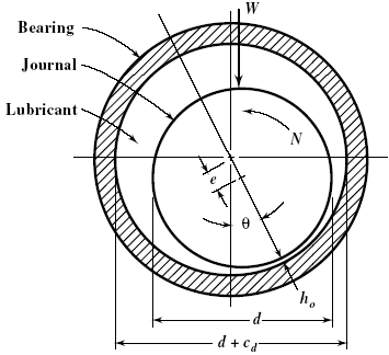
Figure 1
In operation plain journal bearing load is supported by a high pressure oil region as shown in figure 2. Each line in the pressure profile represents an oil pressure vector at the centerline of the bearing. The sum of the vertical components add up to the applied load and the horizontal components cancel out for equilibrium. Oil inlet ports are placed in areas of minimum pressure.
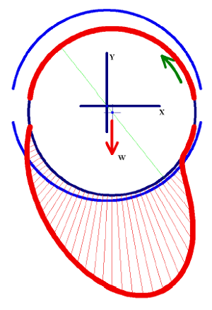
Figure 2
The following formulas provide a complete lubrication analysis which forms the basis for the bearing design.
Bearing Pressure Formula:
pb = W / ( K l d)
Where:
pb = Bearing pressure (psi)
K = 1 for single oil hole
K = 2 for central groove
W = load, lbs
l = bearing length as defined in Fig. 1, inches
d = journal diameter, inches
The following table is intended as a general guide only. The allowable unit pressure depends upon operating conditions, especially in regard to lubrication, design of bearings, workmanship, velocity, and nature of load.
|
Bearing Type
Service |
Pressure
psi (MPa) |
|---|---|
|
Electric Motor & Generator
Bearings (General) |
100–200
(0.69–1.38) |
|
Turbine & Reduction Gears
|
100–250
(0.69–1.72) |
|
Heavy Line Shafting
|
100–150
(0.69–1.03) |
|
Locomotive Axles
|
300–350
(2.07–2.41) |
|
Light Line Shafting
|
15–35
(0.103–0.241) |
|
Diesel Engine, Main
|
800–1500
(5.52–10.34) |
|
Diesel Engine
Rod |
1000–2000
(6.89–13.79) |
|
Wrist Pins
|
1800–2000
(12.41–13.79) |
|
Automotive, Main Bearings
|
500–700
(3.45–4.83) |
|
Automotive, Rod Bearings
|
1500–2500
(10.34–17.24) |
|
Centrifugal Pumps
|
80–100
(0.55–0.689) |
|
Aircraft Rod Bearings
|
700–3000
(4.83–20.68) |
Clearance modulus formula:
m = cd / d
cd = Diametrical clearance (in)
d = journal diameter, (in)
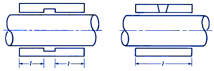
Figure 3
Length to diameter ration formula:
l/d
Typical l/d Ratios
| Service |
l/d
|
| Reciprocating Engine, Gas and Diesel, Main Bearing |
0.3 - 1.0
|
| Generators and Motors |
1.2 - 2.5
|
| Turbogenerators |
0.8 - 1.5
|
| Machine Tools |
2.0 - 3.0
|
| Light Shafting |
2.5 - 3.5
|
| Heavy Shafting |
2.0 - 3.0
|
| Steam Engine Main Bearings |
1.5 - 2.5
|
| Steam EngineCrank and Wrist Pins |
1.0 - 1.3
|
Assumed operating temperature formula:
tb = tin + Δ ta
Where:
tin = inlet temperature of oil in °F
Δta = assumed temperature rise of oil in bearing in °F. An initial assumption of 20°F is usually made.
Absolute Viscosity of Oil vs Temperature Chart Z (Centipoises)
Open: Absolute Viscosity of Oil vs Temperature Chart
Bearing Pressure Parameter formula (required to find the eccentricity ratio):
p' = [ 6.9 ( 1000 m )2 pb ] / Z N
Where:
where N = rpm
Eccentricity Ratio ∈, use P' and l/d to determine 1/( 1 - ∈) from table link below
Torque parameter T, using 1/( 1 - ∈) and l/d See Chart links below:
Torque parameter, T′, vs. eccentricity ratio, 1(1 −∈) journal bearing Chart #1
Torque parameter, T′, vs. eccentricity ratio, 1(1 −∈) journal bearing Chart #2
Friction Torque T, Formulae:
Tf = ( T' r2 Z N ) / ( 6900 ( 1000 m )
Where:
r = Journal radius, inches
Friction Horse power Pf Formulae:
Pf = ( K Tf N l ) / 63,000
Where:
K=1 for single oil hole, 2 for central groove.
Factor X: This factor is used in the calculation of the lubricant flow and can either be estimated from Table below or calculated by:
X = 0.1837 / ( α c )
Where:
α = oil density in pounds per cubic inch
c = specific heat of lubricant in Btu/lb/°F
|
Temperature
|
X Factor |
|
100
|
12.9 |
|
150
|
12.4 |
|
200
|
12.1 |
|
250
|
11.8 |
|
300
|
11.5 |
Total Flow of Lubricant required QR (gal/min) formula:
QR = X ( Pf ) / Δta
Bearing Capacity Number Cn Formula:
Cn = ( l / d )2 / ( 60 P' )
Flow Factor q, obtained from table/curve given in link below:
Flow factor, q, vs. bearing capacity number, Cn& journal bearings.
Hydrodynamic Flow of lubricant Q1 given in gallons per minute calculated from formula:
Q1 = ( N l cd q d ) / 294
Pressure flow of lubricant Q2 given in gallons per minute calculated from formula:
Q2 = [ K2 ps cd3 d ( 1 + 1.5∈2 ) ] / ( Z l )
Where:
K2 = 1.64 × 10⁵ for single oil hole
K2 = 2.35 × 10⁵ for central groove
ps =oil supply pressure
Total flow of lubricant Q formula:
Q = Q1 + Q2
Bearing temperature rise Δt given in degrees F formula:
Δt = ( X Pf ) / Q
Minimum oil film thickness given in inches formula:
ho = 0.5 Cd ( 1 - ∈)
Notation Used
c = specific heat of lubricant, Btu/lb/degree F
cd = diametral clearance, inches
Cn = bearing capacity number
d = journal diameter, inches
e = eccentricity, inches
ho = minimum film thickness, inch
K = constants
l = bearing length
L= actual length of bearing, inches
m = clearance modulus
N = rpm
pb = unit load, psi
ps = oil supply pressure, psi
Pf = friction horsepower
P′ = bearing pressure parameter
q = flow factor
Q1 = hydrodynamic flow, gpm
Q2 = pressure flow, gpm
Q = total flow, gpm
Qnew = new total flow, gpm
QR = total flow required, gpm
r = journal radius, inches
Δt = actual temperature rise of oil in bearing, °F
Δta = assumed temperature rise of oil in bearing, °F
Δtnew = new assumed temperature rise of oil in bearing, °F
tb = bearing operating temperature, °F
tin = oil inlet temperature, °F
Tf = friction torque, inch-pounds/inch
T′ = torque parameter
W= load, pounds
X = factor
Z = viscosity, centipoises
∈= eccentricity ratio — ratio of eccentricity to radial clearance
α = oil density, lbs/inch3
References:
- Machinery's Handbook, 29th Edition
- Understanding Journal Bearings, Malcolm E. Leader, P.E. Applied Machinery Dynamics Co.
- Theory and Practice of Lubrication for Engineers by Dudley D. Fuller, Wiley and Sons, 1984, ISBN 0- 471-04703-1
- Bearing Design and Application by Donald F. Wilcock and E. Richard Booser, McGraw Hill, 1957, 195, LC number 56-9641
Link to this Webpage:
© Copyright 2000 -
2024, by Engineers Edge, LLC
www.engineersedge.com
All rights reserved
Disclaimer |
Feedback
Advertising
| Contact