Related Resources: calculators
Interference Pressure Mechanical Tolerances Variability Equations and Calculator
Engineering, Manufacturing Tolerance Limits Fits Charts
Interference Pressure Mechanical Tolerances Variability Equations and Calculator.
Mechanical Tolerances and Fit Terminology:
When the radial interference (δ) and interface radius (R) is known, the interface pressure (p) can be calculated using equations provided on Thick Wall Cylinder Press or Shrink Fits Equations and Calculator ( Eq. 5) depending on whether the collar and shaft are made of the same material, and depending on whether the shaft is solid or hollow.
Preview: Interference Pressure from Industry Mechanical Tolerances Calculator
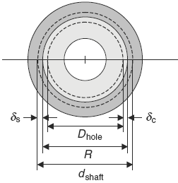
Figure 1
The radial interference (δ) and the interface radius (R) are actually determined from interference fits established by ANSI (American National Standards Institute) standards. There are ANSI standards for both the U.S. customary and metric systems of units.
As the interference (δ) is associated with the changes in the radial dimensions, it can be expressed in terms of the outside diameter dshaft of the shaft and the inside diameter Dhole of the collar given as:
Eq 1
δ = 0.5 ( dshaft - Dhole ) = δc + | δs |
By convention, uppercase letters are used for the dimensions of the hole in the collar,
whereas lowercase letters are used for the dimensions of the shaft. Also, the radial increase (δc) is always positive and the radial decrease (δs ) is always negative, which is why the
absolute value of (δs ) is added to (δc).
Fit Standards. For either the U.S. customary or metric systems of units, the web page General Mechanical Tolerance Table Charts for Standard Shaft Hole Fits contains the standards for press or shrink fits. To summarize, fits are separated into five categories:
1. Loose running and sliding fits
2. Locational clearance fits
3. Locational transition fits
4. Locational interference fits
5. Force or drive and shrink fits
Only for the fifth category, force or drive and shrink fits, does a significant interface
pressure (p) develop between the shaft and collar assembly depending on the materials of the shaft and collar, and whether the shaft
is hollow or solid. Note that if the interface pressure (p) exceeds the yield stress of either
the collar or the shaft, plastic deformation takes place and the stresses are different than the
interface pressure calculated.
When using specific fit standards, whether U.S. customary or metric, the radial interference (δ) given by Eq. 1 needs to be separated into two different calculations. There needs to be a calculation of the maximum radial interference (δmax) to be expected that is given by:
Eq. 2
δmax = 0.5 ( dmax shaft - Dmin hole )
where (dmax shaft) is the maximum diameter of the shaft and (Dmin hole) is the minimum diameter of the hole in the collar. There should also be a calculation of the minimum radial interference (δmin) to be expected and given by:
Eq. 3
δmin = 0.5 ( dmin shaft - Dmax hole )
where (dmin shaft) is the minimum diameter of the shaft and Dmax hole ) is the maximum diameter of the hole in the collar. Many times the minimum radial interference (δmin) is zero, so the interface pressure (p) will also be zero.
The interface pressure exerted by the interference
Eq. 4
pmax = ( E δmax ) / ( 2 R ) [ 1 - ( R / ro ) 2 ]
pmin = ( E δmin ) / ( 2 R ) [ 1 - ( R / ro ) 2 ]
Related:
- Preferred Tolerances & Fits Chart ANSI B4.1 Calculator RC - LT Fits | GD&T Tolerances
- Press Fit Engineering and Design Calculator
- Table of Metric Shaft Tolerances per. ISO 286 Chart Calculator
Source:
Marks' Calculations for Machine Design,
Thomas H. Brown, Jr. Ph.D., PE
Faculty Associate
Institute for Transportation Research and Education
NC State University
Raleigh, North Carolina
Link to this Webpage:
© Copyright 2000 -
2024, by Engineers Edge, LLC
www.engineersedge.com
All rights reserved
Disclaimer |
Feedback
Advertising
| Contact