Related Resources: calculators
Helical Compression Spring Critical Frequency Critical Frequency Formula and Calculator
Helical Compression Spring Critical Frequency Formula and Calculator
Helical springs, such as those used in the valve trains of internal combustion engines, can fail if the frequency of loading coincides with the natural, or critical, frequency of the spring, called resonance. Different end-conditions, like those summarized in Table 1, produce different critical frequencies. To avoid problems, it is usually recommended that the spring design be such that its critical frequency is 15 to 20 times the frequency of the applied cyclic loading frequency.
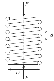
Helical Compression Spring
Preview Helical Compression Spring Critical Frequency Calculator
For a helical spring positioned between flat parallel surfaces, where one of the surfaces is driven by a sinusoidal forcing function, the critical frequency ( f cr) in cycles per second (Hz) is given by the following formula:
Eq 1
f cr = 0.5 ( k / m )0.5
The mass (m) can be found by multiplying the density (ρ) of the spring material times its volume. The development of an expression for the mass of the active part of a spring is given by the following formula:
Eq. 2
m = density · volume
m = ρ A l m
Where:
A = π d2 / 4
l = π D Na
m = ρ π d2 D Na / 4
Including the expression for the the number of active coils ( Na ) into mass formula:
Na = ( d4 G ) / ( 8 D3 k )
thus:
Eq. 3
m = ( ρ π d6 G ) / ( 32 D2 k )
Substitute the expression for the mass (m) Eq. 3 into expression for critical frequency ( f cr) Eq. 1:
Eq 4
( f cr) = ( D K ) / ( π d3 ) [ 8 / ( ρ G ) ]0.5
As stated earlier, multiply the critical frequency by 15 to 20 to avoid resonance with the
frequency of the cyclic loading on the spring.
End-Condition Constant (α) Helical Springs - Table 1
| α | End Condition |
| 0.5 | Both ends supported on flat parallel surfaces |
| 0.7 | One end supported on flat surface, other end hinged |
| 1 | Both ends hinged |
| 2 | One end support on flat surface, other end free |
Where:
f cr = Critical frequency (Hz),
m = mass of active pat of spring,
k = spring constant (lb/in, N/m),
ρ = density (slug/ft3, kg/m3),
Na = number of active coils in spring,
d = diameter of spring wire (in, m),
D = mean diameter of coil helical spring (in, m),
G = shear modulus of
elasticity (lbs/in2, N/m2),
FOS = Spring multiplier applied to cyclic
loading frequency (15 to 20).
Related:
- Spring Terminology and Definitions
- Belleville Spring Washer Equation and Calculator
- Spring Types and Materials Review
- Morrison's Spring Tables Design Reference
- Leaf Spring Design and Engineering Strength of Materials
- Coil Spring Engineering Design Application
- Helical Compression Spring Design Equations and Calculator
- Compression Spring Assembly Operating Life and Reliability Equations and Calculator
- Shock Loading Helical Springs Formulas and Calculator
Source:
Mark's Calculations for Machine Design
Thomas H. Brown, Jr.
Faculty Associate
Institute for Transportation Research and Education
NC State University
Raleigh, North Carolina
Link to this Webpage:
© Copyright 2000 -
2024, by Engineers Edge, LLC
www.engineersedge.com
All rights reserved
Disclaimer |
Feedback
Advertising
| Contact