Related Resources: calculators
Forced Air Flow Convection Cooling Fan Air Flow Required Equations and Calculator
Heat Transfer Engineering and Design
Thermodynamics Engineering
Forced Air Flow Convection Cooling. Fan Air Flow Required for Heat Sinking Formulas and Calculator.
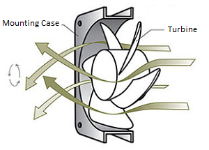
Forced air cooling with a fan of electronic components is often required over the heat transfer provided by natural convection cooling.
Benefits include:
- Reduction in the temperature of the air in the vicinity of the components being cooled.
- Improvement in the heat transfer coefficient of the components transferring heat to the air surrounding them.
Preview: Forced Air Flow Convection Cooling. Fan Air Flow Required for Heat Sinking Calculator
Ultimately best method to to determine cooling requirements is by actual test of the equipment to be cooled; a good approximation of the amount of air required can be determined from the mass flow relationship:
q = w Cp (to - ti) - Equation 1
w, mass airflow:
w = CFM x density
By incorporating conversion factors and specific heat and density for sea level, the heat dissipation equation is arrived at:
Q = 3.16 q / (to - ti) - Equation 2
Where:
q = amount of heat absorbed by the air in BTU/hr
Q = in cubic feet per minute
w = mass flow of air in lb/hr
Cp = specific heat of air in BTU/lb °F
to = operating temperature desired in °F
ti = Initial or ambient temperature in °F
v = Air flow in ft3/min (CFM)
This equation also yields the following formula, which is more directly applied to:
Q = ( 178.4 ti W ) / ( (to - ti) Pb ) - Equation 3
Where:
Q = airflow required in cubic feet per minute
ti = inlet temperature in R (R = °F + 460°)
Δt = (to - ti) temperature rise across the equipment in °F
kW = power to be dissipated in the equipment in kilowatts
Pb = barometric pressure at the air inlet in inches of Hg
Here it is assumed that all of the heat to be dissipated is picked up by the air; i.e. conduction and radiation as well as natural convection effects on the external surfaces of the equipment are ignored.
For standard conditions of 70°F and 29.92" Hg, the equation above reduces to the familiar:
Q = (3160*KW)/ Δt - Equation 4
Recognizing that a given cooling application has numerous design considerations, a temperature rise of 15°F will usually yield effective cooling without incurring penalties of over sizing of the air moving device.
Determining System Impedance
After the airflow has been determined, the amount of resistance to it must be found. This resistance to flow is referred to as system impedance and is expressed in static pressure as a function of flow in CFM. A typical system impedance curve, in most electronic equipment, follows what is called the "square law," which means that static pressure changes as a square function of changes in the CFM. For most forced air cooling application, the system curve is calculated by:
P = KrQn - Equation 5
where:
P = static pressure
K = load factor
r = Fluid Density
Q = Flow
n = constant; Let n=2; approximating a turbulent system.
Related:
- Convective Heat Transfer Convection Equation and Calculator
- Heat Transfer Practical Approach
- Combined Overall Heat Transfer Coefficient Equation
- Overall Heat Transfer Coefficient Table Charts and Equation
- Convective Heat Transfer Coefficient Equation Review
References:
- Cooling of Electronic Equipment, Allen W. Scott
- Guide Manual of Cooling Methods for Electronic Equipment
Link to this Webpage:
© Copyright 2000 -
2024, by Engineers Edge, LLC
www.engineersedge.com
All rights reserved
Disclaimer |
Feedback
Advertising
| Contact