Related Resources: calculators
Fluid Energy Loss in Fittings and Valves Formula, Calculator and Tables
Fluid Flow Table of Contents
Hydraulic and Pneumatic Knowledge
Fluid Energy Loss in Fittings and Valves Formula, Calculator and Tables.
There are two standard ways to calculate the energy lost in fittings and valves: the resistance coefficient method, and the equivalent length method. The method chosen will depend on what information is provided with the fitting to be analyzed.
Resistance Coefficient Method: Resistance coefficients are commonly reported by the manufacturers of liquid fittings and valves. The following equations and Table 26 (or manufacturer’s data) can be used to calculate friction loss in terms of resistance coefficient. There are methods that use up to 3 different resistance coefficients to improve the accuracy of the calculation.
Preview: Fluid Energy Loss in Fittings and Valves Calculator
hl = KF ( v2 / ( 2 g ) )
KF = ƒ ( Le / D )
where:
v = average velocity,
hl = head loss in units of length,
KF = resistance coefficient
for the fitting or valve,
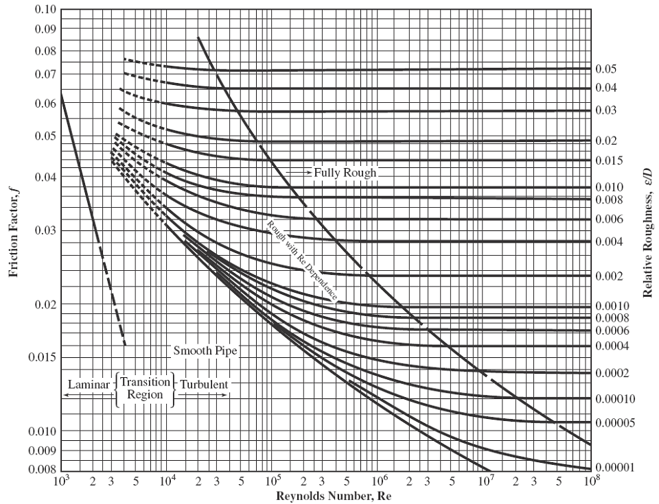
ƒ = friction factor given in the Moody diagram,
Figure 4,
g = gravity (32.174 ft/sec2),
Le / D = equivalent length ratio given in table 1
Equivalent Length Ratio (Le/D) for Liquid Fittings and Valves
Table 1
Valve or Fitting Type |
Le / D |
Elbow |
30 |
Swing Check Valve |
100 |
Street Elbow |
50 |
Ball Check Valve |
150 |
Long Radius Elbow |
20 |
Foot Valve (hinged) |
75 |
45° Elbow |
16 |
Close Return Bend |
50 |
Tee (Flow Thru Run) |
20 |
Tee (Flow Thru Branch) |
60 |
Butterfly Valve (< 8") |
45 |
Globe Valve |
340 |
Ball Valve |
3 |
Gate Valve |
8 |
Gate Valve, 1/2 Closed |
160 |
Equivalent Length Method: Pressure loss can be calculated for systems based on the equivalent length of straight pipe representing all pipe, fittings, and valves in the circuit. Equivalent lengths of some common fittings and valves for liquids can be found in Table 2 and 3.
Table 2Nominal Pipe Size (in.) |
Elbows |
|||||
90° Std. |
45° Std. |
90° Long Radius |
90° Street |
45° Street |
Square Corner |
|
| 1⁄4 |
0.9 |
0.5 |
0.6 |
1.5 |
0.8 |
1.7 |
1⁄2 |
1.6 |
0.8 |
1.0 |
2.6 |
1.3 |
3.0 |
3⁄4 |
2.1 |
1.1 |
1.4 |
3.4 |
1.8 |
3.9 |
1 |
2.6 |
1.4 |
1.7 |
4.4 |
2.3 |
5.0 |
1-1⁄4 |
3.5 |
1.8 |
2.3 |
5.8 |
3.0 |
6.5 |
1-1⁄2 |
4.0 |
2.1 |
2.7 |
6.7 |
3.5 |
7.6 |
2 |
5.5 |
2.8 |
4.3 |
8.6 |
4.5 |
9.8 |
2-1⁄2 |
6.2 |
3.3 |
5.1 |
10.3 |
5.4 |
11.7 |
3 |
7.7 |
4.1 |
6.3 |
12.8 |
6.6 |
14.6 |
4 |
10.1 |
5.4 |
8.3 |
16.8 |
8.7 |
19.1 |
6 |
15.2 |
8.1 |
12.5 |
25.3 |
13.1 |
28.8 |
8 |
20.0 |
10.6 |
16.5 |
33.3 |
17.3 |
37.9 |
10 |
25.1 |
13.4 |
20.7 |
41.8 |
21.7 |
47.6 |
12 |
29.8 |
15.9 |
24.7 |
49.7 |
25.9 |
56.7 |
Table 3
| Nominal Pipe Size (in.) |
Standard Tee | |
| Flow thru Run |
Flow thru Branch |
|
| 1⁄4 | 0.6 | 1.8 |
| 1⁄2 | 1.0 | 4.0 |
| 3⁄4 | 1.4 | 5.1 |
| 1 | 1.7 | 6.0 |
| 1-1⁄4 | 2.3 | 6.9 |
| 1-1⁄2 | 2.7 | 8.1 |
| 2 | 4.3 | 12.0 |
| 2-1⁄2 | 5.1 | 14.3 |
| 3 | 6.3 | 16.3 |
| 4 | 8.3 | 22.1 |
| 6 | 12.5 | 32.2 |
| 8 | 16.5 | 39.9 |
| 10 | 20.7 | 50.1 |
| 12 | 24.7 | 59.7 |
Figure 4 Moody Diagram
Click on Image to Enlarge
Link to this Webpage:
© Copyright 2000 -
2024, by Engineers Edge, LLC
www.engineersedge.com
All rights reserved
Disclaimer |
Feedback
Advertising
| Contact