Related Resources: calculators
Cup Anemometer Wind Measurement Formulae and Calculator
Power Transmission and Technology Menu
Applications and Design
Cup Anemometer Wind Measurement Equation and Calculator
The anemometer, most commonly used in wind energy measurements is the cup anemometer. It consists of three (or four) equally spaced cups attached to a centrally rotating vertical axis through spokes (Fig. 1). The cups are hemispherical or conical in shape and made with light weight material. This is basically a drag device. When kept in the flow, the wind exerts drag force on the cups.
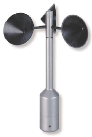
Cup Anemometer Figure 1
Eq. 1
FD = CD · 0.5 · A · ρa · V2
where CD is the drag coefficient, A is the area of cup exposed to the wind, ρa is the air density and V is the wind velocity.
As the drag coefficient of concave surface is more than on the convex surface, the cup with its concave side facing the wind experiences more drag force. This causes the cups to rotate on its central axis. The intensity of rotation is directly proportional to the velocity of incoming wind.
This is further calibrated in terms of wind velocity, which can be directly sensed and recorded.
Although these anemometers can sustain a variety of harsh environments, they have some limitations. It accelerates quickly with the wind but retards slowly as wind ceases. Due to this slow response, cup anemometers do not give reliable measurement in wind gusts. As the drag force is proportional to the density, any changes in the air density will affect the accuracy of metered velocity. Nevertheless of these limitations, cup anemometers are widely used for measuring wind velocity in meteorological as well as wind energy applications.
Related:
- Hot-Wire Anemometer Flow Detector Review
- Wind Turbine Power and Torque Equation and Calculator
- Wind Turbine Power From Wind
- Wind Power Generation and Wind Power Turbine Design
- Aerodynamics of Wind Turbine
- Wind Energy Fundamentals
- Wind Energy, Renewable Energy and the Environment
- Hydraulic Turbine Power Formulae and Calculator
Source:
Sathyajith Mathew
Wind Energy
Fundamentals, Resource Analysis and Economics
Link to this Webpage:
© Copyright 2000 -
2024, by Engineers Edge, LLC
www.engineersedge.com
All rights reserved
Disclaimer |
Feedback
Advertising
| Contact