Related Resources: calculators
Bolt Preload Torsion Stress Formulas and Calculator per. MIL-HDBH-60
Torque Design Menu
Bolt Preload Equations
Bolt Fastener Preload Torsion Load Stress Formulas and Calculator per. MIL-HDBH-60
Bolt Preloads may be applied directly by axial loading or by shear loading by turning of the nut or bolt. When preload is applied by turning of nuts or bolts, a torsion load component is added to the desired axial bolt load. This combined loading increases the tensile stress on the bolt.
Preview: Bolt Fastener Preload Torsion Load Stress Calculator (Premium membership required for calculator)
It is frequently assumed that the additional torsion load component dissipates quickly after the driving force is removed and, therefore, can be largely ignored. This assumption may be reasonable for fasteners loaded near to or beyond yield strength, but for critical applications where bolt tension must be maintained below yield, it is important to adjust the axial tension requirements to include the effects of the preload torsion. For this adjustment, the combined tensile stress (von Mises stress) Ftc in psi (MPa) can be calculated from the following:
Equation 1
Ftc = [ Ft2 + 3 Fs2 ]1/2
Where:
Ftc = Combined tensile stress (von Mises stress), psi (MPa)
Ft = Axial tensile stress, psi (MPa)
Fs = Shear stress, psi (MPa)
Some of the torsion load on a bolt, acquired when applying a preload, may be released by spring back when the wrenching torque is removed. The amount of relaxation depends on the friction under the bolt head or nut. With controlled back turning of the nut, the torsional load may be reduced or eliminated without loss of axial load, reducing bolt stress and lowering creep and fatigue potential. However, calculation and control of the back-turn angle is difficult, so this method has limited application and cannot be used for short bolts because of the small angles involved.
For relatively soft work-hardenable materials, tightening bolts in a joint slightly beyond yield will work-harden the bolt to some degree. Back turning of the bolt to the desired tension will reduce embedment and metal flow and improve resistance to preload loss.
Combined tensile stress, for use with single-start Unified inch screw
Equation 2
Ftc = Ft [ 1 +3 ( ( 1.96 + 2.31 µ ) / ( 1 - 0.325 P / d2 ) )2 - 1.96 ]1/2
Single-start UNJ screw threads in accordance with MIL-S-8879 have a thread stress diameter equal to the bolt pitch diameter. For these threads, Ftc can be calculated from:
Equation 3
Ftc = Ft [ 1 +3 ( ( 0.637 P) / d2 + 2.31 µ )2 ]1/2
Where:
Ft = Axial tensile stress, psi
µ = coefficient of friction between threads
P = Thread pitch, 1/n
n = thread per inch
d2 = bolt-thread pitch diameter, in
Both Equations (2) and (3) are derived from Equation (1); thus, the quantity within the radical [ ]1/2 represents the proportion of increase in axial bolt tension resulting from preload torsion. In these equations, tensile stress due to torsion load application becomes most significant when the thread friction, μ, is high.
Coefficients of friction bolts and nuts
Bolt/Nut Materials |
Lubricant |
Coefficient of Friction, μ ± 20% |
Steel1 |
Graphite in petrolatum or oil Molybdenum disulfide grease Machine oil |
0.07 0.11 0.15 |
Steel,1 cadmium-plated |
None added |
0.12 |
Steel,1 zinc-plated |
None added |
0.17 |
Steel1/bronze |
None added |
0.15 |
Corrosion-resistant steel or nickel-base alloys/silver plated materials |
None added |
0.14 |
Titanium/steel1 |
Graphite in petrolatum |
0.08 |
Titanium |
Molybdenum disulfide grease |
0.00 |
1“Steel” includes carbon and low-alloy steels but not corrosion-resistant steels.
Where two materials are separated by a slash (/), either may be the bolt material; the other is the nut material.
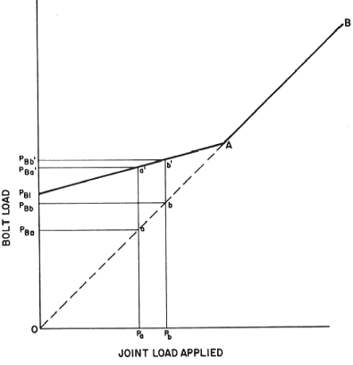
Bolt Load in joint with applied axial load, Figure 1
Reference / Open (Free Membership minimum required for this document):
Military Handbook, Threaded Fasteners - Tightening to Proper Tension MIL-HDBK-60
Related:
- Torque Wrench Adapter for Reduced Arm Equation and Calculation
- Torque Clamp Force Calculator
- Stud Preload Calculator
- Bolt Preload Tension Equation and Calculator
- Bolt Preload Tension Force Calculator
- Torque vs Tension Bolts Table Chart SAE J429 Bolts
- Bolt Multiple Diameters Change of Length Under Axial Force Formula and Calculator
Link to this Webpage:
© Copyright 2000 -
2024, by Engineers Edge, LLC
www.engineersedge.com
All rights reserved
Disclaimer |
Feedback
Advertising
| Contact