Related Resources: calculators
Bolt Multiple Diameters Change of Length Under Axial Force Formula and Calculator
Bolt & Screw Torque Charts and Equations
Bolt Multiple Diameters Change of Length Under Axial Force Formula and Calculator
We also have to make some assumptions concerning cross-sectional areas of the bolt when computing change in length. The body area is no mystery; it’s merely equal to π D2 / 4, where D is the nominal diameter of the fastener.
For the cross-sectional area of the threads, however, we must use the effective or ‘‘stress area’’.
Preview: Bolt Multiple Diameters Change of Length Under Axial Tension Loading Calculator
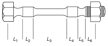
Figure 1 Each cross section of a complex fastener must be computed separately.
The combined change in length of the bolt will be equal to the sum of the changes in each section:
Equation 1
ΔLc = ΔL1 + ΔL2 + ΔL3 + ΔLn...
Hooke’s law tells that the change in one section will be:
Equation 2
ΔL = (F · L ) / ( E · A )
Where
ΔL = change in length (in., mm)
A = cross-sectional area (in.2, mm2)
L = length of the section (in., mm)
E = modulus of elasticity (psi, GPa)
F = applied tensile force (lb, N)
If the fastener has a more complex shape, as shown in Figure 1, then additional sections must be computed, but there is otherwise no change in the procedure.
Since the various sections are connected in series, they each see the same force, so we can combine Equations 1 and 2 above and write
Equation 3
ΔLc = Fp [ L1 / ( E A1 ) + L2 / ( E A2 ) + L3 / ( E A3 ) + L4 / ( E A4 ) + L5 / ( E A5 ) + L6 / ( E A6 ) + Ln / ( E An ) + ...]
Where
ΔLc = change in length of the body under load (in., mm) F
Fp = tension in bolt (lb, N)
Related:
- Force Required Strip Bolt Threads Formula and Calculator
- Combined Thread and Body Bolt Elongation Under Preload Formula and Calculator
- Bolt Elongation Formula and Calculator per. ASME PCC-1
- Elongation Chart for Common Bolting Materials
- Calculating Assembly Torque per ISO 68 & ISO 724
- Screw Stress Area 100 ksi & Greater
- Bolt Stress Area less Than 100 ksi
- Bolt Elongation Equation and Calculator while under Axial Stress
- ISO Hardware Engineering Data
- ANSI Hardware Engineering Data
- Hardware Supplier Manufacturer
- Strength of Materials
Reference:
Introduction to the Design and Behavior of Bolted Joints Non-Gasketed Joints, Forth Edition
Founding Editor
L. L. Faulkner
Columbus Division, Battelle Memorial Institute,
Department of Mechanical Engineering
The Ohio State University
Columbus, Ohio
Link to this Webpage:
© Copyright 2000 -
2024, by Engineers Edge, LLC
www.engineersedge.com
All rights reserved
Disclaimer |
Feedback
Advertising
| Contact