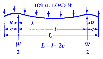
Beam Deflection and Stress Equations Calculator for Beam Supported on Both Ends With Overhanging Supports of equal Length and Uniform Loading
Beam Deflection and Stress Formula and Calculators
Area Moment of Inertia Equations & Calculators
Structural Beam Deflection, Stress, Bending Equations and calculator for a Beam Supported on Both Ends With Overhanging Supports of equal Length and Uniform Loading .
Open
Deflection and Stress Beam For Supported on Both Ends Calculator
Beam Stress between nearest support point and outer end
![]()
Beam Stress between the two supports
![]()
Beam Stress at load center
![]()
Beam Stress at supports
![]()
If cross-section is constant, the greater of these is the maximum stress.
If l is greater than 2c, the stress is zero at points on both sides of the center.
![]()
If Beam cross-section is constant and if l = 2.828c, the stresses at supports and center are equal and opposite, and are:
![]()
Beam Deflection between support point and outer end
![]()
![]()
Beam Deflection between supports
![]()
Beam Deflection at the ends
![]()
Deflection at center
![]()
If l is between 2c and 2.449c, there are maximum upward deflections at points
![]()
on both sides of the center, which are,
![]()
Where:
| E = | Modulus of Elasticity | psi | (N/mm2) |
| I = | Moment of Inertia | in4 | (mm4) |
| W = | Beam Load | lbs | (N) |
| s = | Beam Stress at the cross-section being evaluated | Lbs/in2 | (N/mm2) |
| y = | Beam Deflection | inches | (mm) |
| x = | Some distance as indicated | inches | (mm) |
| u = | Some distance as indicated | inches | (mm) |
| c = | Some distance as indicated | inches | (mm) |
| L = | Some distance as indicated | inches | (mm) |
| l = | Some distance as indicated | inches | (mm) |
Z = |
section modulus of the cross-section of the beam = I/z | in3 | (mm3) |
z = |
distance from neutral axis to extreme fiber (edge) | inches | (mm) |
- Please note letter "l" (lower case "L") is different than "I" (Moment of Inertia).
- Beam Deflections apply only to constant cross sections along entire length.
References:
- Any Machinery's Handbook published since 1931 or,
- Machinery's Handbook, 21st Edition, Page 405 or,
- Machinery's Handbook, 23st Edition, Page 261 or,
- Machinery's Handbook, 27st Edition, Page 26
Related
- Axial Load Capacities for Single Plates Calculator
- Beam Deflection Equations / Calculator Supported on Both Ends Uniform Loading
- Beam Deflection Equations / Calculator Supported on Both Ends Single Load at Center
- Beam Deflection Equations / Calculator Supported on Both Ends Loaded at any Location
- Beam Stress Deflection Equations / Calculator - Fixed at Both Ends, Load at Center
- Beam Stress Deflection Equations / Calculator - Fixed at Both Ends, Load at any Location
- Beam Stress Deflection Equations / Calculator with Uniform Loading
- Beam Deflection Stress Deflection Equations / Continuous Beam, with Two Unequal Spans, Unequal, Uniform Loads
- Beam Stress Beam Deflection Equations / Calculator - Continuous Beam, with Two Equal Spans, Uniform Load
- Beam Stress Beam Defection Simply Supported on Both Ends Under Superimposed Loading Equations
Link to this Webpage:
© Copyright 2000 -
2024, by Engineers Edge, LLC
www.engineersedge.com
All rights reserved
Disclaimer |
Feedback
Advertising
| Contact