Constant Force Spring Design Equations and Calculator
A constant-force spring is a spring for which the force it exerts over its range of motion is a constant. That is, it does not obey Hooke's law. Generally constant-force springs are constructed as a rolled ribbon of spring steel such that the spring is relaxed when it is fully rolled up. As it is unrolled, the restoring force comes primarily from the portion of the ribbon near the roll. Because the geometry of that region remains nearly constant as the spring unrolls, the resulting force is nearly constant.
A conical spring can be made to have a constant rate by creating the spring with a variable pitch. Putting a larger pitch in the larger OD coils and a smaller pitch in the smaller OD coils will force the spring to collapse all the coils at the same rate when compressed.
Design:
A constant force spring is a roll of pre stressedstrip which exerts a nearly constant restraining force to resist uncoiling (Figures 1 and 2). The force is constant because the change in the radius of curvature is constant. This is true if the change in coil diameter due to buildup is disregarded. Long extension capabilities, constant torque and virtual absence of inter coilfriction have led many designers to specify constant force springs in such applications as brush springs for motors, counterbalance springs for window sashes and carriage return springs for typewriters. Constant force motor springs are also used to drive mechanisms for timers, movie cameras and cable retractors.
 |
Typical Constant Force Springs Figure 1 |
Extension Type Constant force extension springs are supplied as a coil of strip with a natural radius of curvature Rn (Figure 3). If such a spring is mounted on a drum, the drum diameter should be 10 to 20% larger than its natural diameter. One and one-half wraps should remain on the drum at maximum extension. The active portion of the material is approximately equal to 1.25 times the diameter D0. Consequently, the spring does not reach its rated load until the extension is greater than 1.25 D0 (Figure 1).
Radius of curvature changes from Rn to infinity in the active portion and requires a clearance. Recommended distance from drum center to the straight section is 0.8 times the diameter D0 (Figure 3). The strip becomes unstable at long extensions and should be guided to prevent twisting or kinking on recoil. Idler pulleys must be larger in diameter than the natural diameter and should never be used to cause back-bending against the natural radius of curvature (Figure 4).
 |
General Load Deflection Curves for Spring Types. Figure 2 |
Equations:
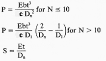
Where:
P = Load (N, lbs)
E = Modulus of Elasticity (Pa, psi)
D1 = outside coil diameter, (mm, in)
D0 = drum diameter, (mm, in)
b = Spring Width, (mm, in)
c = Design constant factor - to compensate for the cross curvature occurring in the extension form. (material design characteristic).
Dn = Diameter 1,2 or 3, (mm, in)
N = Number of coil turns
b = Width mm (mm, in)
t = Thickness (mm, in)
S = Stress MPa (psi)
L = 1.56N (D0 + Dn) = f + 5Dn [mm (in)]
For typical designs, ratio b/t = 100 and ratio D0/Dn = 1.2.
 |
Typical Design Constant Force Spring Figure 3 |
 |
Recommended Idler Pulley design when using constant force springs Figure 4 |
Bibliographical References
1. Johnson, Leonard, G., The Statistical Treatment of Fatigue Experiments. New York:
Elsevier Publishing Co., 1964.
2. Little, R. E. and E. H. Jebe., Statistical Design of Fatigue Experiments. New York: John
Wiley & Sons, 1975.
3. Wahl, A. M., Mechanical Springs, 2nd ed. New York: McGraw-Hill, 1963.
4. Berry, W. R., Spring Design: A Practical Treatment. London: Emmot & Co., 1961.
5. Almen, J. O. and A. Laszlo., "The Uniform Section Disc Spring," A.S.M.E Transactions,
vol.58, no. 4, (May 1936), pp. 305-314.
6. Blake, A., Design of Curved Members for Machines. New York: Industrial Press, 1966.
7. Bisshopp, K. E. and D. C. Drucker., "Large Deflections of Cantilever Beams", Quarterly of
Applied Mathematics, vol. 3, no. 3, (1945), p. 272.
8. Maker, J. H., "Steel Springs," Metals Handbook. 9th ed. Metals Park: ASM, vol.1, (1978)
pp. 283-313.
9. Design and Manufacture of Volute Springs. New York: SAE, 1945.
10. Peterson, R. E., Stress Concentration Factors. New York: John Wiley & Sons, (1974), p
231.
11. Maier, Karl, W., "Dynamic Loading of Compression Springs," Product Engineering,
(January 1954), pp. 162-167. "Dynamic Loading of Compression Springs," (March 1955),
pp. 162-72. "Surge Waves in Compression Springs," (August 1957), pp. 167-174.
- Design Equations of Belleville Washer Springs
- Leaf Spring Design and Engineering Strength of Materials
- Constant Force Spring Design and Equations
- Coil Spring Engineering Design Application
- Helical Compression Spring Design Equations and Calculator
- Shock Loading Helical Springs Formulas and Calculator
- Helical Spring Fatigue Loading and Factor of Safety Formulas and Calculator
- Series and Parallel Spring Forces Calculator
Link to this Webpage:
© Copyright 2000 -
2024, by Engineers Edge, LLC
www.engineersedge.com
All rights reserved
Disclaimer |
Feedback
Advertising
| Contact