Leaf Spring Design and Engineering
Simple Supported Leaf Spring:


Uniform Width Leaf Spring Equation

Non-Uniform Width Leaf Spring Equation
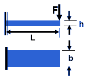
Simply supported leaf of Lozenge shape for which the maximum stress and maximum deflection are known. From the stress and deflection equations the thickness of the spring plate, h, can be obtained as,

The σmax is replaced by design stress σdes. Similarly, δmax is replaced by δdes.
E = The Modulus of Elasticity material property and depends on the type of spring material chosen.
L = The characteristic length of the spring. Therefore, once the design parameters, given on the left side of the above equation, are fixed the value of plate thickness, h can be calculated. Substitution of h in the stress equation above will yield the value of plate width b.
F = Force applied to leaf spring.
b = Width of leaf spring
h = Height or thickness of leaf spring

In the similar manner h and b can be calculated for leaf springs of different support conditions and beam types.
Laminated Leaf Springs
One of the challenges of the uniform strength beam, say Lozenge shape, is that the value of width b sometimes is too large to accommodate in a machine assembly. One practice is that instead of keeping this large width one can make several slices and put the pieces together as a laminate. This is the concept of laminated spring. The illustration below shows the concept of formation of a laminated spring.

Laminated Leaf Spring
The Lozenge shaped plate is cut into several longitudinal strips, as indicated above. The central strip, marked 1 is the master leaf which is placed at the top. Then two pieces, marked 2 are put together, side by side to form another leaf and placed below the top leaf. In the similar manner other pairs of strips, marked 3 and 4 respectively are placed in the decreasing order of strip length to form a laminated spring. Here width of each strip, b N is given as,

Where:
N = The number of spring strips or layers.
b = Width of leaf spring
In practice, strips of width, bN and lengths, stay equal to layer1, layer2 etc., as shown in the example, are cut and put in the laminated form. The stress and deflection equations for a laminated spring is,

Where p and q are:
Simply supported beam: p = 3 and q = 3
Cantilever beam: p = 6 and q = 6
L = The characteristic length of the spring. Therefore, once the design parameters, given on the left side of the above equation, are fixed the value of plate thickness, h can be calculated. Substitution of h in the stress equation above will yield the value of plate width b.
F = Force applied to leaf spring.
b = Width of leaf spring
h = Height or thickness of leaf spring
N = Number of spring strips or leafs
It should be noted that the ends of the leaves are not sharp and pointed, as shown below. In fact they are made blunt or even made straight to increase the load bearing capacity. This change from ideal situation does not have much effect on the stress equation. However, small effect is there on the deflection equation.

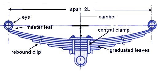
The Illustration above shows a laminated semi- elliptic spring. The top leaf is known as the master leaf. The eye is provided for attaching the spring with another machine member. The amount of bend that is given to the spring from the central line, passing through the eyes, is known as camber. The camber is provided so that even at the maximum load the deflected spring should not touch the machine member to which it is attached. The camber shown in the figure is known as positive camber. The central clamp is required to hold the leaves of the spring. However, the bolt holes required to engage the bolts to clamp the leaves weaken the spring to some extent. Rebound clips help to share the load from the master leaf to the graduated leaf.
Heavy loads - Leaf Spring Design
In order to carry heavy loads a few more additional full length leaves are placed below the master leaf for heavy loads. Such alteration from the standard laminated leaf spring, does not change the stress value, but deflection equation requires some correction.

Where, correction in deflection, δc is given as,

Where:
m= Nf / N
Nf = Number of full length leaf layers
N = Total number or leaf layers in spring
F = Force applied to Leaf Spring