Related Resources: hardware
Standard Metric Keys Keyways for Metric Bores with One Key
Engineering Hardware Design Data
ISO Hardware Specifications Table
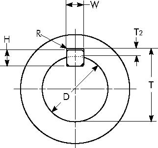
Standard Metric Keys & Keyways for Metric Bores with One Key
|
Metric Key & Keyway Dimensions Per ISO/R773 – P9 Width Tolerance H
|
||||||||||
|---|---|---|---|---|---|---|---|---|---|---|
|
Shaft Diameter
|
Key Size
|
Keyway Width
|
Keyway Depth
|
Keyway Radius
|
||||||
|
"D"
|
Nominal
|
Hub "W"
|
Hub ""
|
"R"
|
||||||
|
Over
|
Thru
|
Width "W"
|
Height "H"
|
Nominal
|
Min
|
Max
|
Min
|
Max
|
Min
|
Max
|
|
6
|
8
|
2
|
2
|
2
|
-.031
|
-.006
|
1.0
|
1.1
|
0.08
|
0.16
|
|
8
|
10
|
3
|
3
|
3
|
-.031
|
-.006
|
1.4
|
1.5
|
0.08
|
0.16
|
|
10
|
12
|
4
|
4
|
4
|
-.042
|
-.012
|
1.8
|
1.9
|
0.08
|
0.16
|
|
12
|
17
|
5
|
5
|
5
|
-.042
|
-.012
|
2.3
|
2.4
|
0.16
|
0.25
|
|
17
|
22
|
6
|
6
|
6
|
-.042
|
-.012
|
2.8
|
2.9
|
0.16
|
0.25
|
|
22
|
30
|
8
|
7
|
8
|
-.051
|
-.015
|
3.3
|
3.5
|
0.16
|
0.25
|
|
30
|
38
|
10
|
8
|
10
|
-.051
|
-.015
|
3.3
|
3.5
|
0.25
|
0.40
|
|
38
|
44
|
12
|
8
|
12
|
-.061
|
-.018
|
3.3
|
3.5
|
0.25
|
0.40
|
|
44
|
50
|
14
|
9
|
14
|
-.061
|
-.018
|
3.8
|
4.0
|
0.25
|
0.40
|
|
50
|
58
|
16
|
10
|
16
|
-.061
|
-.018
|
4.3
|
4.5
|
0.25
|
0.40
|
|
58
|
65
|
18
|
11
|
18
|
-.061
|
-.018
|
4.4
|
4.6
|
0.25
|
0.40
|
|
65
|
75
|
20
|
12
|
20
|
-.074
|
-.022
|
4.9
|
5.1
|
0.40
|
0.60
|
|
75
|
85
|
22
|
14
|
22
|
-.074
|
-.022
|
5.4
|
5.6
|
0.40
|
0.60
|
|
85
|
95
|
25
|
14
|
25
|
-.074
|
-.022
|
5.4
|
5.6
|
0.40
|
0.60
|
|
95
|
110
|
28
|
16
|
28
|
-.074
|
-.022
|
6.4
|
6.6
|
0.40
|
0.60
|
|
110
|
130
|
32
|
18
|
32
|
-.088
|
-.026
|
7.4
|
7.6
|
0.40
|
0.60
|
|
130
|
150
|
36
|
20
|
36
|
-.088
|
-.026
|
8.4
|
8.7
|
0.70
|
1.00
|
|
150
|
170
|
40
|
22
|
40
|
-.088
|
-.026
|
9.4
|
9.7
|
0.70
|
1.00
|
|
170
|
200
|
45
|
25
|
45
|
-.088
|
-.026
|
10.4
|
10.7
|
0.70
|
1.00
|
|
200
|
230
|
50
|
28
|
50
|
-.088
|
-.026
|
11.4
|
11.7
|
0.70
|
1.00
|
|
230
|
260
|
56
|
32
|
56
|
-.106
|
-.032
|
12.4
|
12.7
|
1.20
|
1.60
|
|
260
|
290
|
63
|
32
|
63
|
-.106
|
-.032
|
12.4
|
12.7
|
1.20
|
1.60
|
|
290
|
330
|
70
|
36
|
70
|
-.106
|
-.032
|
14.4
|
14.7
|
1.20
|
1.60
|
|
330
|
380
|
80
|
40
|
80
|
-.106
|
-.032
|
15.4
|
15.7
|
2.00
|
2.50
|
|
380
|
440
|
90
|
45
|
90
|
-.124
|
-.037
|
17.4
|
17.7
|
2.00
|
2.50
|
|
440
|
500
|
100
|
50
|
100
|
-.124
|
-.037
|
19.5
|
19.8
|
2.00
|
2.50
|
| Metric Key & Keyway Dimensions Per ISO/R773 – D10 Width Tolerance | ||||||||||
|---|---|---|---|---|---|---|---|---|---|---|
|
Shaft Diameter
|
Key Size
|
Keyway Width
|
Keyway Depth
|
Keyway Radius
|
||||||
|
"D"
|
Nominal
|
Hub "W"
|
Hub "T"
|
"R"
|
||||||
|
Over
|
Thru
|
Width "W"
|
Height "H"
|
Nominal
|
Min
|
Max
|
Min
|
Max
|
Min
|
Max
|
|
6
|
8
|
2
|
2
|
2
|
+.020
|
+.060
|
1.0
|
1.1
|
0.08
|
0.16
|
|
8
|
10
|
3
|
3
|
3
|
+.020
|
+.060
|
1.4
|
1.5
|
0.08
|
0.16
|
|
10
|
12
|
4
|
4
|
4
|
+.030
|
+.078
|
1.8
|
1.9
|
0.08
|
0.16
|
|
12
|
17
|
5
|
5
|
5
|
+.030
|
+.078
|
2.3
|
2.4
|
0.16
|
0.25
|
|
17
|
22
|
6
|
6
|
6
|
+.030
|
+.078
|
2.8
|
2.9
|
0.16
|
0.25
|
|
22
|
30
|
8
|
7
|
8
|
+.040
|
+.098
|
3.3
|
3.5
|
0.16
|
0.25
|
|
30
|
38
|
10
|
8
|
10
|
+.040
|
+.098
|
3.3
|
3.5
|
0.25
|
0.40
|
|
38
|
44
|
12
|
8
|
12
|
+.050
|
+.120
|
3.3
|
3.5
|
0.25
|
0.40
|
|
44
|
50
|
14
|
9
|
14
|
+.050
|
+.120
|
3.8
|
4.0
|
0.25
|
0.40
|
|
50
|
58
|
16
|
10
|
16
|
+.050
|
+.120
|
4.3
|
4.5
|
0.25
|
0.40
|
|
58
|
65
|
18
|
11
|
18
|
+.050
|
+.120
|
4.4
|
4.6
|
0.25
|
0.40
|
|
65
|
75
|
20
|
12
|
20
|
+.065
|
+.149
|
4.9
|
5.1
|
0.40
|
0.60
|
|
75
|
85
|
22
|
14
|
22
|
+.065
|
+.149
|
5.4
|
5.6
|
0.40
|
0.60
|
|
85
|
95
|
25
|
14
|
25
|
+.065
|
+.149
|
5.4
|
5.6
|
0.40
|
0.60
|
|
95
|
110
|
28
|
16
|
28
|
+.065
|
+.149
|
6.4
|
6.6
|
0.40
|
0.60
|
|
110
|
130
|
32
|
18
|
32
|
+.080
|
+.180
|
7.4
|
7.6
|
0.40
|
0.60
|
|
130
|
150
|
36
|
20
|
36
|
+.080
|
+.180
|
8.4
|
8.7
|
0.70
|
1.00
|
|
150
|
170
|
40
|
22
|
40
|
+.080
|
+.180
|
9.4
|
9.7
|
0.70
|
1.00
|
|
170
|
200
|
45
|
25
|
45
|
+.080
|
+.180
|
10.4
|
10.7
|
0.70
|
1.00
|
|
200
|
230
|
50
|
28
|
50
|
+.080
|
+.180
|
11.4
|
11.7
|
0.70
|
1.00
|
|
230
|
260
|
56
|
32
|
56
|
+.100
|
+.220
|
12.4
|
12.7
|
1.20
|
1.60
|
|
260
|
290
|
63
|
32
|
63
|
+.100
|
+.220
|
12.4
|
12.7
|
1.20
|
1.60
|
|
290
|
330
|
70
|
36
|
70
|
+.100
|
+.220
|
14.4
|
14.7
|
1.20
|
1.60
|
|
330
|
380
|
80
|
40
|
80
|
+.100
|
+.220
|
15.4
|
15.7
|
2.00
|
2.50
|
|
380
|
440
|
90
|
45
|
90
|
+.120
|
+.260
|
17.4
|
17.7
|
2.00
|
2.50
|
|
440
|
500
|
100
|
50
|
100
|
+.120
|
+.260
|
19.5
|
19.8
|
2.00
|
2.50
|
Where:
T = D + T2
Related:
- Standard External Metric Thread and Fastener Sizes M 0.25 - M 1.4
- ANSI Woodruff Keys
- Shaft with Four Keyways Torque Applied Deformation and Stress Equations and Calculator
- Shaft with Keyway Torque Applied Deformation and Stress Equations and Calculator
- Metric Key Keyway Dimensions
- Parallel Key and Taper Keys Dimensions
- Shaft Keyway Shear and Yield Strength Formulae and Calculator
- Shaft (Arbor) Keyway Dimension Size Data - ANSI/ASME B94.19-1997
- Shaft Arbor and Keyseat Dimensional Data American National Standard Keys and Keyways
- Standard Metric Keys Keyways for Metric Bores with One Key
- Keyway Cutter Hole Keyway Dimensional Data for MIlling Centers and Arbors - ANSI/ASME B94.19-1997
- Keyway Stresses for Non-metallic Gears and Shafts Formulas and Calculator
Link to this Webpage:
© Copyright 2000 -
2024, by Engineers Edge, LLC
www.engineersedge.com
All rights reserved
Disclaimer |
Feedback
Advertising
| Contact