Internal Retaining Snap Ring Sizes and Groove Design Bore Sizes 1.562 - 3.000
The following is Internal Retaining Snap Ring Sizes and Groove Design chart for sizes 1.562 to 3.000

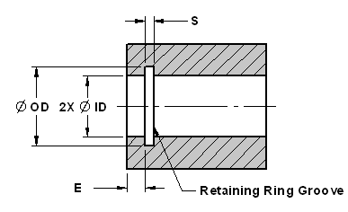
Retaining Ring Grove Dimensional Requirements

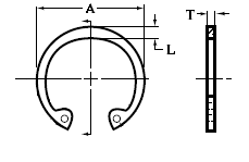
Internal Retaining ( Snap ) Ring Sive Designations
(All data is in inches.)
| Housing Bore | Ring | Ring Groove | ||||||||
|---|---|---|---|---|---|---|---|---|---|---|
Dia. |
Diameter |
Thickness |
Diameter |
Width |
Edge |
|||||
ID |
A |
Tol. | T |
Tol. | OD |
Tol. | S |
Tol. | E |
Tol. |
1.562 |
1.734 |
+.035 ----
+.040
+.055 |
.062 |
+.003
|
1.658 |
+.005
----
+.006
|
.068 |
+.004
----
+.005
|
.144 |
Not more |
Reference: Industrial Retaining Snap Rings, 3100 Series.
All dimensions are in inches. Depth of groove d = (OD-ID)/2. Thickness indicated is for unplated rings; for most plated rings, the maximum ring thickness will not exceed the minimum groove width (S) minus 0.0002 inch. Standard material: carbon spring steel (SAE 1060-1090).
Ring Free Diameter Tolerances: For shaft sizes 0.125 through 0.250, +0.002, -0.004; for sizes 0.276 through 0.500, +0.002, -0.005; for sizes 0.551 through 1.023, +0.005, -0.010; for sizes 1.062 through 1.500, +0.010, -0.015; for sizes 1.562 through 2.000, +0.013, -0.020; for sizes 2.062 through 2.500, +0.015, -0.025; for sizes 2.559 through 5.000, +0.020, -0.030; for sizes 5.250 through 6.000, +0.020, -0.040; for sizes 6.250 through 6.750, +0.020, -0.050; for sizes 7.000 and 7.500, +0.050, -0.130.
Ring Thickness Tolerances: For shaft sizes 0.125 and 0.156, ±0.001; for sizes 0.188 through 1.500, ±0.002; for sizes 1.562 through 5.000, ±0.003; for sizes 5.250 through 6.000, ±0.004; for sizes 6.250 through 7.500, ±0.005.
Groove Diameter Tolerances: For shaft sizes 0.125 through 0.250, ±0.0015; for sizes 0.276 through 0.562, ±0.002; for sizes 0.594 through 1.023, ±0.003; for sizes 1.062 though 1.500, ±0.004; for sizes 1.562 through 2.000, ±0.005; for sizes 2.062 through 5.000, ±0.006; for sizes 5.250 through 6.000, ±0.007; for sizes 6.250 through 7.500, ±0.008.
Groove Width Tolerances: For shaft sizes 0.125 through 0.236, +0.002, -0.000; for sizes 0.250 through 1.023, +0.003, -0.000; for sizes 1.062 through 2.000, +0.004, -0.000; for sizes 2.062 through 5.000, +0.005, -0.000; for sizes 5.250 through 6.000, +0.006, -0.000; for sizes 6.250 through 7.500, +0.008, -0.000.
Related Resources: