ANSI Metric Tapered Retaining Snap Rings per. ANSI B27.7 Size Chart
Basic metric size retaining snap rings per. ANSI B27.7 size chart. Includes Ring and groove design data, groove dimensional and tolerance information. Retaining snap ring is a fastener that holds components or assemblies onto a shaft or in a housing/bore when installed in a groove. Once installed, the exposed portion acts as a shoulder which retains the specific component or assembly. Circlips are a type of retaining ring. Retaining rings are typically made from carbon steel, stainless steel or beryllium copper and may feature a variety of finishes for corrosion protection depending on the type of environment in which they are used.
|
ANSI Metric Tapered Retaining Snap Rings per. ANSI B27.7 Size Chart
Shaft Diam |
Ring |
Groove |
||||
Free Dia. |
Thick ness |
Dia. |
Width |
Depth |
Edge Margin |
|
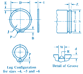
| S | D | t | G | W | d ref | Z min |
|---|---|---|---|---|---|---|
| 4 | 3.60 | 0.25 | 3.80 | 0.32 | 0.1 | 0.3 |
| 5 | 4.55 | 0.4 | 4.75 | 0.5 | 0.13 | 0.4 |
| 6 | 5.45 | 0.4 | 5.70 | 0.5 | 0.15 | 0.5 |
| 7 | 6.35 | 0.6 | 6.60 | 0.7 | 0.20 | 0.6 |
| 8 | 7.15 | 0.6 | 7.50 | 0.7 | 0.25 | 0.8 |
| 9 | 8.15 | 0.6 | 8.45 | 0.7 | 0.28 | 0.8 |
| 10 | 9.00 | 0.6 | 9.40 | 0.7 | 0.30 | 0.9 |
| 11 | 10.00 | 0.6 | 10.35 | 0.7 | 0.33 | 1.0 |
| 12 | 10.85 | 0.6 | 11.35 | 0.7 | 0.33 | 1.0 |
| 13 | 11.90 | 0.9 | 12.30 | 1.0 | 0.35 | 1.0 |
| 14 | 12.90 | 0.9 | 13.25 | 1.0 | 0.38 | 1.2 |
| 15 | 13.80 | 0.9 | 14.15 | 1.0 | 0.43 | 1.3 |
| 16 | 14.70 | 0.9 | 15.10 | 1.0 | 0.45 | 1.4 |
| 17 | 15.75 | 0.9 | 16.10 | 1.0 | 0.45 | 1.4 |
| 18 | 16.65 | 1.1 | 17.00 | 1.2 | 0.50 | 1.5 |
| 19 | 17.60 | 1.1 | 17.95 | 1.2 | 0.53 | 1.6 |
| 20 | 18.35 | 1.1 | 18.85 | 1.2 | 0.58 | 1.7 |
| 21 | 19.40 | 1.1 | 19.80 | 1.2 | 0.60 | 1.8 |
| 22 | 20.30 | 1.1 | 20.70 | 1.2 | 0.65 | 1.9 |
| 23 | 21.25 | 1.1 | 21.65 | 1.2 | 0.67 | 2.0 |
| 24 | 22.20 | 1.1 | 22.60 | 1.2 | 0.70 | 2.1 |
| 25 | 23.10 | 1.1 | 23.50 | 1.2 | 0.75 | 2.3 |
| 26 | 24.05 | 1.1 | 24.50 | 1.2 | 0.75 | 2.3 |
| 27 | 24.95 | 1.3 | 25.45 | 1.4 | 0.78 | 2.3 |
| 28 | 25.80 | 1.3 | 26.40 | 1.4 | 0.80 | 2.4 |
| 30 | 27.90 | 1.3 | 28.35 | 1.4 | 0.83 | 2.5 |
| 32 | 29.60 | 1.3 | 30.20 | 1.4 | 0.90 | 2.7 |
| 34 | 31.40 | 1.3 | 32.00 | 1.4 | 1.00 | 3.0 |
| 35 | 32.30 | 1.3 | 32.90 | 1.4 | 1.05 | 3.1 |
Shaft Diam |
Ring |
Groove |
||||
Free Dia. |
Thickness |
Dia. |
Width |
Depth |
Edge Margin |
|
| S | D | t | G | W | d ref | Z min |
|---|---|---|---|---|---|---|
| 36 | 33.25 | 1.3 | 33.85 | 1.4 | 1.06 | 3.2 |
| 38 | 35.20 | 1.3 | 35.8 | 1.4 | 1.10 | 3.3 |
| 40 | 36.75 | 1.6 | 37.7 | 1.75 | 1.15 | 3.4 |
| 42 | 38.80 | 1.6 | 39.6 | 1.75 | 1.20 | 3.6 |
| 43 | 39.65 | 1.6 | 40.5 | 1.75 | 1.25 | 3.8 |
| 45 | 41.60 | 1.6 | 42.4 | 1.75 | 1.30 | 3.9 |
| 46 | 42.55 | 1.6 | 43.3 | 1.75 | 1.35 | 4.0 |
| 48 | 44.40 | 1.6 | 45.2 | 1.75 | 1.40 | 4.2 |
| 50 | 46.20 | 1.6 | 47.2 | 1.75 | 1.40 | 4.2 |
| 52 | 48.40 | 2.0 | 49.1 | 2.15 | 1.45 | 4.3 |
| 54 | 49.9 | 2.0 | 51.0 | 2.15 | 1.50 | 4.5 |
| 55 | 50.6 | 2.0 | 51.8 | 2.15 | 1.60 | 4.8 |
| 57 | 52.9 | 2.0 | 53.8 | 2.15 | 1.60 | 4.8 |
| 58 | 53.6 | 2.0 | 54.7 | 2.15 | 1.65 | 4.9 |
| 60 | 55.8 | 2.0 | 56.7 | 2.15 | 1.65 | 4.9 |
| 62 | 57.3 | 2.0 | 58.6 | 2.15 | 1.70 | 5.1 |
| 65 | 60.4 | 2.0 | 61.6 | 2.15 | 1.70 | 5.1 |
| 68 | 63.1 | 2.0 | 64.5 | 2.15 | 1.75 | 5.3 |
| 70 | 64.6 | 2.4 | 66.4 | 2.55 | 1.80 | 5.4 |
| 72 | 66.6 | 2.4 | 68.3 | 2.55 | 1.85 | 5.5 |
| 75 | 69.0 | 2.4 | 71.2 | 2.55 | 1.90 | 5.7 |
| 78 | 72.0 | 2.4 | 74.0 | 2.55 | 2.00 | 6.0 |
| 80 | 74.2 | 2.4 | 75.9 | 2.55 | 2.05 | 6.1 |
| 82 | 76.4 | 2.4 | 77.8 | 2.55 | 2.10 | 6.3 |
| 85 | 78.6 | 2.4 | 80.6 | 2.55 | 2.20 | 6.6 |
| 88 | 81.4 | 2.8 | 83.5 | 2.95 | 2.25 | 6.7 |
| 90 | 83.2 | 2.8 | 85.4 | 2.95 | 2.30 | 6.9 |
| 95 | 88.1 | 2.8 | 90.2 | 2.95 | 2.40 | 7.2 |
| 100 | 92.5 | 2.8 | 95.0 | 2.95 | 2.50 | 7.5 |
Notes:
All dimensions are in millimeters. Sizes −4, −5, and −6 are available in beryllium copper only.
These rings are designated by series symbol and shaft diameter, thus: for a 4 mm diameter shaft, 3AM1-4; for a 20 mm diameter shaft, 3AM1-20; etc.
Ring Free Diameter Tolerances: For ring sizes −4 through −6, +0.05, −0.10 mm; for sizes −7 through −12, +0.05, −0.15 mm; for sizes −13 through − 26, +0.15, −0.25 mm; for sizes −27 through −38, +0.25, −0.40 mm; for sizes −40 through −50, +0.35, −0.50 mm; for sizes −52 through −62, +0.35, −0.65 mm; and for sizes −65 through −100, +0.50, −0.75 mm.
Groove Diameter Tolerances: For ring sizes −4 through −6, −0.08 mm; for sizes −7 through −10, − mm; for sizes −11 through −15, −0.12 mm; for sizes −16 through −26, −0.15 mm; for sizes −27 through − 36, −0.20 mm; for sizes −38 through −55, −0.30 mm; and for sizes −57 through −100, 0.40 mm.
Groove Diameter F.I.M. (full indicator movement) or maximum allowable deviation of concentricity between groove and shaft: For ring sizes −4 through −6, 0.03 mm; for ring sizes −7 through − 12, 0.05 mm; for sizes −13 through −28, 0.10 mm; for sizes −30 through −55, 0.15 mm; and for sizes −57 through − 00, 0.20 mm.
Groove Width Tolerances: For ring size −4, +0.05 mm; for sizes −5 and −6, +0.10 mm, for sizes − 7 through −38, +0.15 mm; and for sizes −40 through − 100, +0.20 mm.
Groove Maximum Bottom Radii,R: For ring sizes −4 through −6, none; for sizes −7 through −18,
0.1 mm; for sizes −19 through −30, 0.2 mm; for sizes −32 through −50, 0.3 mm; and for sizes −52 through −100, 0.4 mm.
Related Resources:
Link to this Webpage:
© Copyright 2000 -
2024, by Engineers Edge, LLC
www.engineersedge.com
All rights reserved
Disclaimer |
Feedback
Advertising
| Contact