Geometric Dimensioning and Tolerancing GD&T Tool
Geometric Dimensioning & Tolerancing
GD&T Training
GD&T Training Definitions
Mechanical Tolerance Tables, Charts and Design Data
Open (in popup) --> Geometric Tolerance Design & Selection Tool
Software Tool requirements and function:
- Modern web browser.
- Flash 10.0 or higher
- Hover curser over text boxes and select for next option
- Use "Previous Page" function to return to previous web page.
- See bottom of web page for incremental Forward and Backward controls.
This tool will assist in design and selection of the correct geometric tolerances.
The purpose of the tool is to assist the designer in selecting the correct geometric characteristic for a particular application. The decision diagrams are based on the design requirements and the application of datums, geometric tolerances, and modifiers that have been developed. The diagrams are organized to help the user think in terms of design intent and functional requirements, and assist in the development of the contents of feature control frames.
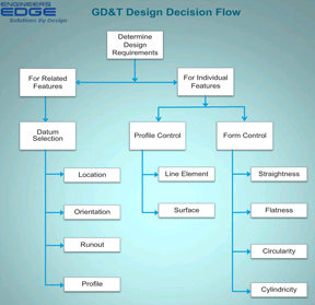
Functional Requirements:
When delineating a designs intent, the designer must consider both the stabilization of the component and the functional requirements of the individual features. In reference to individual features, the Form and Profile controls must be considered. If the application deals with Related Features, the Location Orientation, Runout, and Profile controls should be considered.
Application:
After the application is determined, the designer will be directed to more specific diagrams by clicking on the perspective text button link. Each diagram will prompt the designer to consider additional decisions, such as what needs to be controlled (center plane axis, or surface), functional tolerance to be met, applicable modifiers, and requisite datum modifiers.
Standard:
All geometric tolerance references are in accordance with ASME Y 14.5-2009 standard.
Geometric Tolerance Controls:
The box entitled "Consider Limits of Size" is a reminder to examine the size limits with respect to Rule #1 (Envelope Principle) before applying additional geometric tolerances.
Choosing Form Tolerance Controls:
When form tolerances are required, the diagrams will lead the designer through the various applications and does suggest a variety of potential geometric tolerances as dictated by the design requirements.
Choosing Additional Geometric Tolerances:
Other aspects of each part feature should be considered by the designer for their orientation, location, profile, and runout as they relate to other part features.
Material Modifiers:
Material and geometric function modifiers are integral to geometric tolerances, but are only applicable when applied to features with size. If modifier is not included within the decision diagram then it is not applicable.
Datums:
Datums do not apply to all geometric characteristics or features. Datums are never used with form controls and is reflected within the decision diagrams.
Datum Modifiers:
A feature of size may be selected as a datum and materials modifiers should be considered.
Multiple Datums:
Many applications only require a primary datum, while others may need secondary and tertiary datums. When more than one datum is required, the diagrams loop back until the datums reference framework is satisfied.
The GD&T Tolerance selection tool is arranged as follows:
-
Design Requirements
-
Datums Selections
-
Form Tolerances
-
Orientation Tolerances
-
Location Tolerances
-
Profile Tolerances
-
Runout Tolerances
-
Definitions
Open (in popup) --> Geometric Tolerance Design & Selection Tool
Related Resources:
- General Tolerances Shaft - Holes Fits
- GDT Geometric Dimensioning Tolerancing Basics Training
- GDT Geometric Dimensioning Tolerancing Intermediate Training
- GDT ASME Y14.5-2009 Applications Training
- G&T Geometric Tolerancing ISO 1101 Training
- Online GD&T Fundamentals Training
Link to this Webpage:
© Copyright 2000 -
2024, by Engineers Edge, LLC
www.engineersedge.com
All rights reserved
Disclaimer |
Feedback
Advertising
| Contact